Supply voltage control device for amplifier

a technology of supply voltage control and amplifier, which is applied in the direction of amplifiers, amplifiers with semiconductor devices only, amplifiers with semiconductor devices, etc., can solve the problems of loss of linearity of power amplifier b>2/b>, hard to realize the performance using a typical semiconductor, and the inability to supply the necessary supply voltage to the power amplifier, etc., to achieve linearity and high efficiency. the effect of amplifier

Inactive Publication Date: 2011-07-12
KOKUSA ELECTRIC CO LTD
View PDF5 Cites 14 Cited by
  • Summary
  • Abstract
  • Description
  • Claims
  • Application Information

AI Technical Summary

Benefits of technology

[0033]The present invention is intended to break through the foregoing existing situation. An object of the present invention is to provide a supply voltage control device for an envelope tracking amplifier which can feed a necessary supply voltage to a power amplifier while sustaining high efficiency, and ensure the linearity of the power amplifier.
[0037]A signal resulting from peak hold processing, which is performed on a signal of a predetermined high-frequency component contained in a signal resulting from detection of an envelope relevant to a signal to be amplified by the amplifier, is add to a signal resulting from detection of the envelope of the signal to be amplified by the amplifier. The supply voltage control circuit is activated with a signal resulting from the addition. Therefore, for example, in the supply voltage control device for the envelope tracking amplifier, a necessary supply voltage can be fed to the amplifier (for example, power amplifier) while high efficiency is sustained, and the linearity of the amplifier (for example, power amplifier) can be ensured.
[0039]The direct current feed circuit included in the supply voltage control circuit can attain higher efficiency than, for example, the error amplification circuit can.
[0051]A signal resulting from peak hold processing performed on a signal of a predetermined high-frequency component, which is contained in a signal resulting from detection of an envelope relevant to a signal to be amplified by the amplifier, is added to a signal of a predetermined low-frequency component contained in the signal resulting from detection of the envelope relevant to the signal to be amplified by the amplifier (signal passed by the low-pass filtration unit). The supply voltage control circuit is activated with the signal resulting from the addition. Therefore, for example, in the supply voltage control device for the envelope tracking amplifier, a necessary supply voltage can be fed to the amplifier (for example, power amplifier) while high efficiency is sustained, and the linearity of the amplifier (for example, power amplifier) can be ensured.
[0054]As mentioned above, according to the present invention, for example, in the supply voltage control device for the envelope tracking amplifier, a necessary supply voltage can be fed to an amplifier (for example, power amplifier) while high efficiency is sustained, and the linearity of the amplifier (for example, power amplifier) can be ensured.

Problems solved by technology

It is hard to realize the performance using a typical semiconductor.
Therefore, a necessary supply voltage cannot be fed to the power amplifier 2.
This poses a problem in that the linearity of the power amplifier 2 is lost.

Method used


Image

  • Supply voltage control device for amplifier
  • Supply voltage control device for amplifier
  • Supply voltage control device for amplifier

Examples


first embodiment

[0067]A first embodiment of the present invention will be described below.

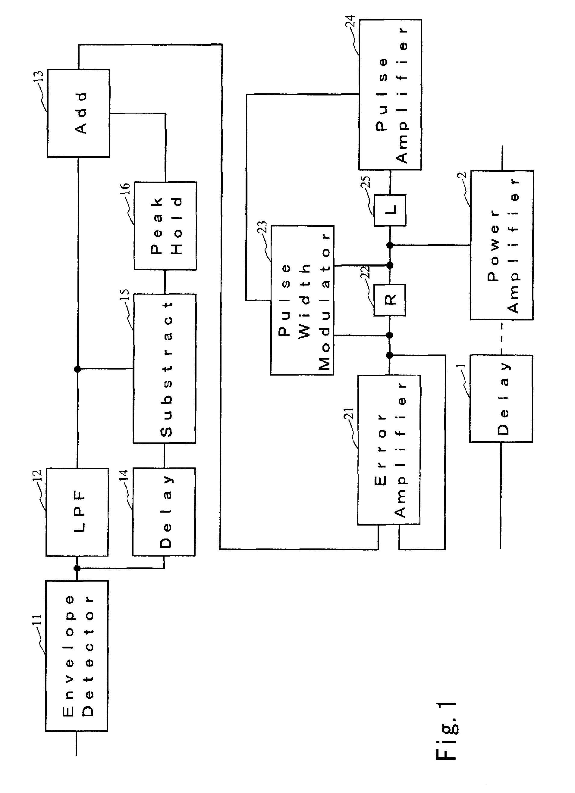
[0068]FIG. 1 shows an example of the constitution of an envelope tracking type power amplification system in accordance with an embodiment of the present invention.

[0069]The power amplification system of the present embodiment includes an envelope detector 11, a low-pass filter (LPF) 12, an adder (Add) 13, an envelope delay circuit (Delay) 14, a subtractor (Subtract) 15, a peak hold circuit (Peak Hold) 16, an error amplifier 21, a resistor (R) 22, a pulse width modulator 23, a pulse amplifier 24, a coil (L) 25, a delay circuit (Delay) 1, and a power amplifier 2.

[0070]Herein, the same signal is inputted to the delay circuit 1 and envelope detector 11. The signal may be varied in terms of, for example, a digital or analog form, or a frequency. More particularly, for example, a mode in which the signal is inputted as an analog signal to each of the delay circuit 1 and envelope detector 11 (examples shown in FIG. ...

second embodiment

[0091]A second embodiment of the present invention will be described below.

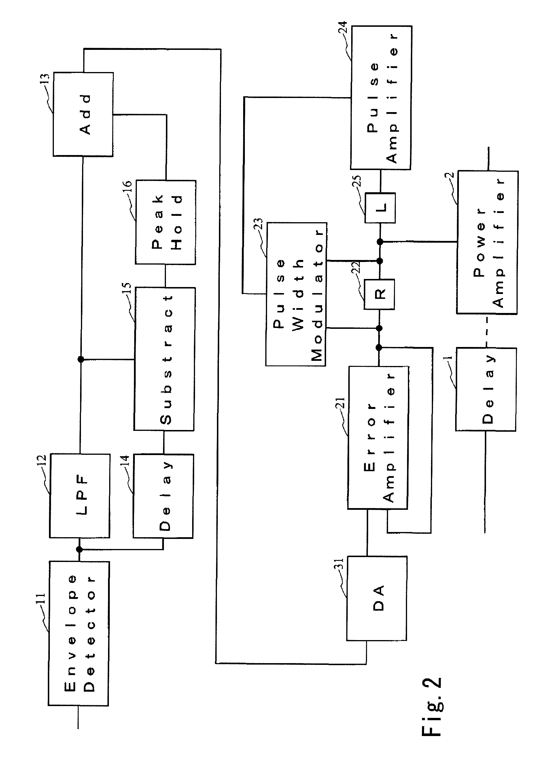
[0092]FIG. 2 shows an example of the constitution of an envelope tracking type power amplification system in accordance with an embodiment of the present invention.

[0093]The power amplification system of the present embodiment includes an envelope detector 11, a low-pass filter (LPF) 12, an adder (Add) 13, an envelope delay circuit (Delay) 14, a subtractor (Subtract) 15, a peak hold circuit (Peak Hold) 16, an error amplifier 21, a resistor (R) 22, a pulse width modulator 23, a pulse amplifier 24, a coil (L) 25, a delay circuit (Delay) 1, a power amplifier 2, and a digital-to-analog converter (DA) 31 that converts a digital signal into an analog signal.

[0094]The constitution of the power amplification system of the present embodiment is identical to that of the power amplification system shown in FIG. 1 except a point that the digital-to-analog converter 31 is interposed between the adder 13 and error amplifie...

third embodiment

[0097]A third embodiment of the present invention will be described below.

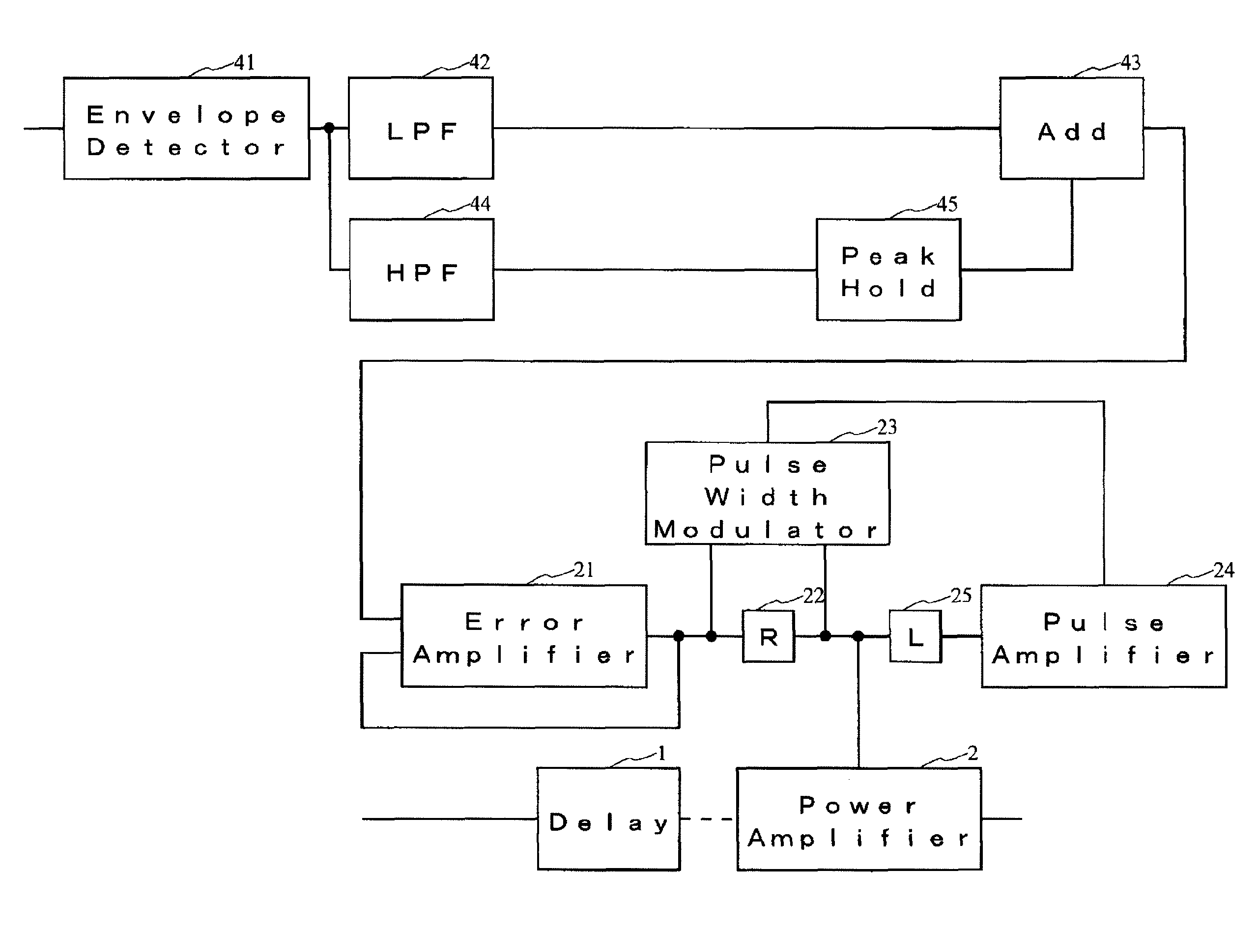
[0098]FIG. 3 shows an example of the constitution of an envelope tracking type power amplification system in accordance with an embodiment of the present invention.

[0099]The power amplification system of the present embodiment includes an envelope detector 41, a low-pass filter (LPF) 42, an adder (Add) 43, a high-pass filter (HPF) 44, a peak hold circuit (Peak Hold) 45, an error amplifier 21, a resistor (R) 22, a pulse width modulator 23, a pulse amplifier 24, a coil (L) 25, a delay circuit (Delay) 1, and a power amplifier 2.

[0100]The configuration of the power amplification system of the present embodiment and the operation thereof are identical to those of the power amplification system shown in FIG. 1 except those relating to the envelope detector 41, low-pass filter 42, adder 43, high-pass filter 44, and peak hold circuit 45. A description of the identical components will be omitted. For convenience' sake,...


PUM


Abstract

A supply voltage control device for an amplifier that controls a supply voltage for the amplifier has been improved. The supply voltage control device includes: a supply voltage control circuit including an error amplification circuit that feeds an error current so as to control the supply voltage for the amplifier, and a direct current feed circuit that feeds a direct current (or the direct current and a current of a low-frequency component); a high-frequency component extraction unit that extracts a predetermined high-frequency component contained in a signal resulting from detection of an envelope relevant to a signal to be amplified by the amplifier; a peak hold unit that performs peak hold processing on a signal of the extracted high-frequency component; and an addition unit that adds up a signal based on the result of detection of the envelope relevant to the signal to be amplified by the amplifier, and the signal resulting from the peak hold processing, and inputs a signal resulting from the addition to the supply voltage control circuit.

Description

BACKGROUND OF THE INVENTION[0001]1. Field of the Invention[0002]The present invention relates to a supply voltage control device for an envelope tracking amplifier. More particularly, the present invention is concerned with a supply voltage control device for an amplifier capable of feeding a supply voltage, which is necessary to a power amplifier, while sustaining high efficiency, and ensuring the linearity of the power amplifier.[0003]2. Description of the Related Art[0004]In recent digital wireless communication systems, a multilevel modulation method in which a mean power of a signal and a peak power thereof largely differ from each other is often adopted in order to raise a transmission speed.[0005]In conventional power amplification systems, when such a signal is handled, a constant voltage making it possible to output the peak power is fed to a power amplifier in order to ensure the linearity of the power amplifier.[0006]However, a time during which the peak power is outputte...

Claims


Application Information

Patent Timeline
Patent Type & Authority Patents(United States)
IPC IPC(8): H03G3/20
CPCH03G3/004
Inventor ITO, KEIJUMIURA, SUSUMU
Owner KOKUSA ELECTRIC CO LTD
Why Eureka
Try Eureka