Methods and apparatus for controlling air flow within a pulse detonation engine

a pulse detonation engine and air flow technology, which is applied in the ignition of the turbine/propulsion engine, the treatment of combustion air/fuel air, and the engine starter, etc., can solve the problems of reducing forward flow, adversely affecting the performance of the combustor, and affecting the combustion performance, so as to facilitate the control of air flow

Active Publication Date: 2011-07-19
GENERAL ELECTRIC CO
View PDF17 Cites 25 Cited by
  • Summary
  • Abstract
  • Description
  • Claims
  • Application Information

AI Technical Summary

Problems solved by technology

However, known unvalved combustors are not designed to restrict backward traveling shock waves generated from the detonation wave and / or the reverse flow that follows the backward traveling shock wave and as such forward flow is reduced.
Because known combustors are not designed to balance air flow through each chamber, the different amounts of air flow may adversely affect the combustor performance.
However, the use of plenums may still result in enough reverse flow and flow-imbalance to adversely affect combustion performance.

Method used


Image

  • Methods and apparatus for controlling air flow within a pulse detonation engine
  • Methods and apparatus for controlling air flow within a pulse detonation engine
  • Methods and apparatus for controlling air flow within a pulse detonation engine

Examples


Embodiment Construction

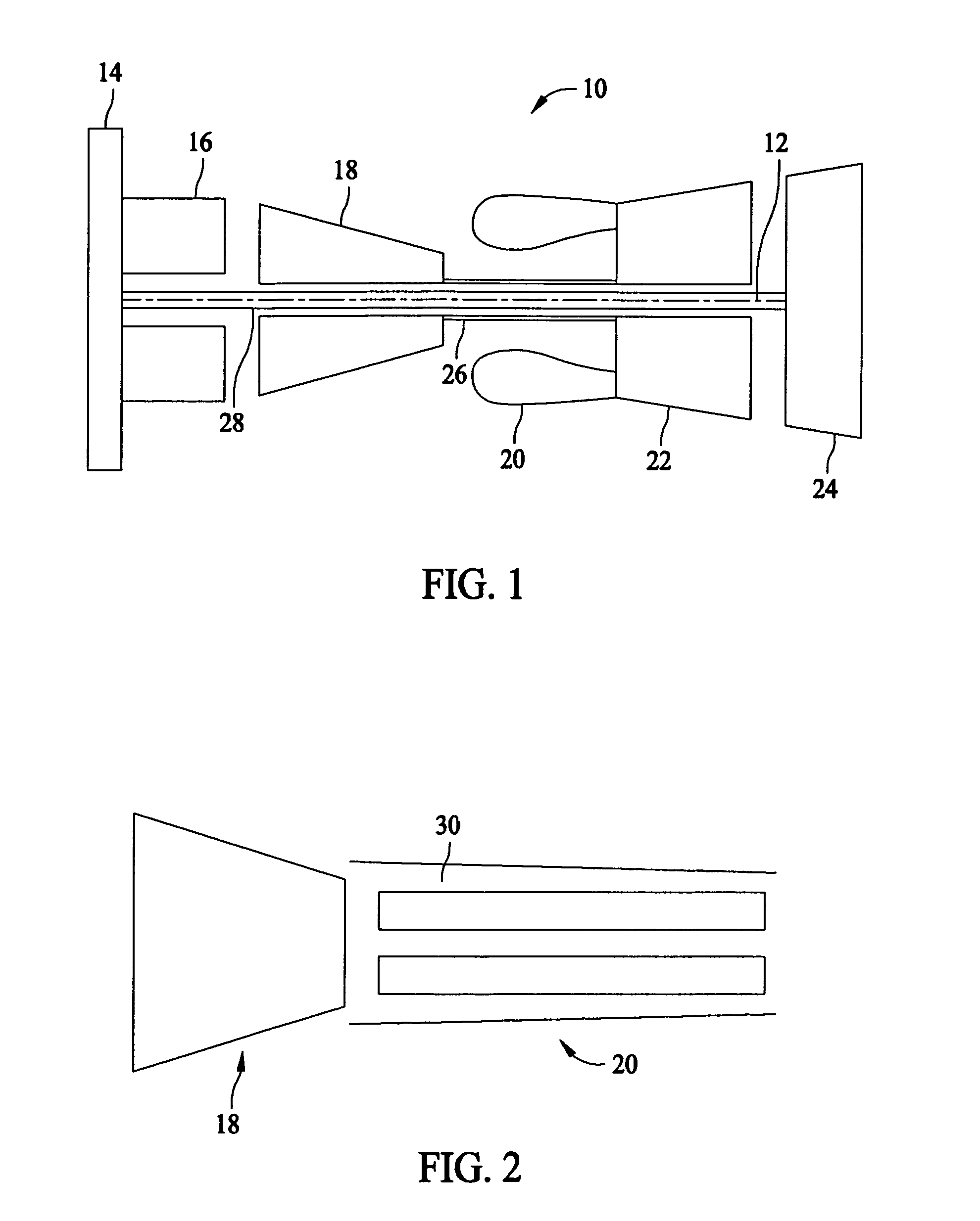
[0014]FIG. 1 is a schematic illustration of an exemplary hybrid pulse detonation-turbine engine 10. Engine 10 includes, in serial axial flow communication and aligned about a longitudinal centerline axis 12, a fan 14, a booster 16, a high pressure compressor 18, and a pulse detonation combustor (PDC) 20, a high pressure turbine 22, and a low pressure turbine 24. High pressure turbine 22 is rotatably coupled to high pressure compressor 18 with a first rotor shaft 26, and low pressure turbine 24 is rotatably coupled to both booster 16 and fan 14 with a second rotor shaft 28, which is disposed within first shaft 26.

[0015]In operation, air flows through fan 14, booster 16, and high pressure compressor 18, and is pressurized by each component in succession. As used herein the term “air” should be understood to mean an oxidizer. For example, and without limitation, air can be oxygen and / or compressed air. In the exemplary embodiment, PDC 20 is configured to receive highly compressed air f...


PUM


Abstract

A flow control device for use with a pulse detonation chamber including an inlet coupled in flow communication with a source of compressed air. The inlet extends at least partially into the chamber to facilitate controlling air flow into the chamber. The device also includes a body portion extending downstream from and circumferentially around the inlet, wherein the body portion is positioned in flow communication with the inlet.

Description

BACKGROUND OF THE INVENTION[0001]This invention relates generally to pulse detonation engines, and more particularly, to methods and apparatus for controlling air flow within a pulse detonation engine.[0002]Known pulse detonation engines generally operate with a detonation process having a pressure rise, as compared to engines operating within a constant pressure deflagration. As such, pulse detonation engines may have the potential to operate at higher thermodynamic efficiencies than may generally be achieved with deflagration-based engines.[0003]At least some known hybrid pulse detonation-turbine engines have replaced the steady flow constant pressure combustor within the engine with a pulse detonation combustor that may include at least one pulse detonation chamber. Although such engines vary in their implementation, a common feature amongst hybrid pulse detonation-turbine engines is that air flow from a compressor is directed into the pulse detonation chamber wherein the air is ...

Claims


Application Information

Patent Timeline
Patent Type & Authority Patents(United States)
IPC IPC(8): F02C7/04
CPCF02C5/02F02C5/11
Inventor RASHEED, ADAMDEAN, ANTHONY JOHN
Owner GENERAL ELECTRIC CO
Why Eureka
Try Eureka