Method and apparatus for treatment of contaminated liquid

a technology for contaminated liquid and treatment methods, applied in the direction of centrifugal force sediment separation, feed/discharge of settling tanks, machines/engines, etc., can solve the problems of slow processing capability of the treatment system, loosening of the material collected on the membrane surface, and clogging of the membrane, so as to facilitate the flow of liquid and achieve the effect of reducing the density of the sludge blanket, occupying less space, and facilitating the flow of liquid

Inactive Publication Date: 2011-07-19
POWELL SCOTT W
View PDF93 Cites 24 Cited by
  • Summary
  • Abstract
  • Description
  • Claims
  • Application Information

AI Technical Summary

Benefits of technology

[0017]The integrated or combined apparatus has many advantages. First, the settling capability of the outer tank as a clarifier / sedimentation tank minimizes the amount of solid particulates that can reach the ultra-filtration units, thereby extending the period of operation of the ultra-filtration units before backwash is required. Additionally, the apparatus of the invention requires only one tank for clarifying and filtering, thus eliminating the need for two separate tanks. In the event the apparatus includes the electrocoagulation function, the apparatus replaces the need for three separate tanks. A clarified liquid is retained within the chamber of the casing and the clarified liquid therein is isolated and not subject to any turbulent flow that could otherwise re-suspend solids in the clarified liquid. Further, the requirement of the liquid flow through the sludge blanket further enhances separation of the solids from the flow of the liquid, since the sludge blanket itself acts as a pre-filter prior to the liquid reaching the filters. Thus, the sludge blanket can be viewed as a secondary filter to capture additional suspended solids. This secondary filtering feature of the apparatus can be selectively controlled by the amount of vacuum that is pulled on the filter units, thereby also providing the capability to adjust ultra-filtration at rates consistent with the capabilities of the installed type of ultra-filtration filters.
[0019]Additionally, it may be desirable to adjust the density of the sludge blanket within the tank to better facilitate a desired flow of liquid through the solid mass. Accordingly, it is also contemplated that one or more vibrators can be attached to the outer surface of the lower portion of the tank. The vibrators will increase the density of the sludge blanket causing the solid material to occupy less space within the lower portion of the tank. It is also contemplated that an auger or stirring assembly can be used to slowly stir the solid mass in order to adjust the density of the solid mass to thereby optimize a flow of liquid through the sludge blanket prior to reaching the chamber of the casing. Stirring is done at a rate however that does not materially increase the amount of suspended solids in the chamber. During this stirring, the vacuum drawn on the filters can be shut off to allow any re-suspended solids to re-settle back to the sludge blanket.
[0020]Depending upon the type of ultra-filtration filters provided, a source of air may be introduced into the tank and to the ultra-filtration filters to maximize operation of the filters and / or to provide additional cleaning capability at which point in time the filters require a backwash cycle.

Problems solved by technology

One particular limitation in the use of a reverse osmosis unit, as well as ultra-filtration units, is that the membranes will become clogged over time, and some reverse flow is required to cause a loosening of the material collected on the membrane surfaces.
The backwash requirement slows the processing capability of the treatment system.
This cleaning requirement further delays the operation of the waste treatment facility.

Method used


Image

  • Method and apparatus for treatment of contaminated liquid
  • Method and apparatus for treatment of contaminated liquid
  • Method and apparatus for treatment of contaminated liquid

Examples


Embodiment Construction

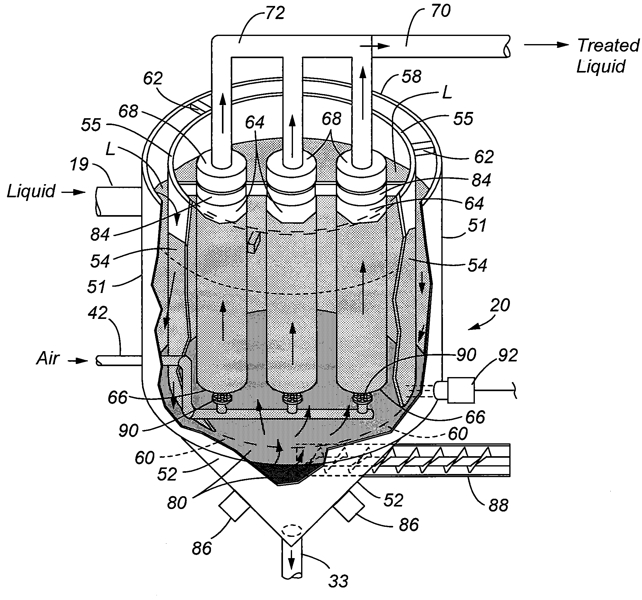
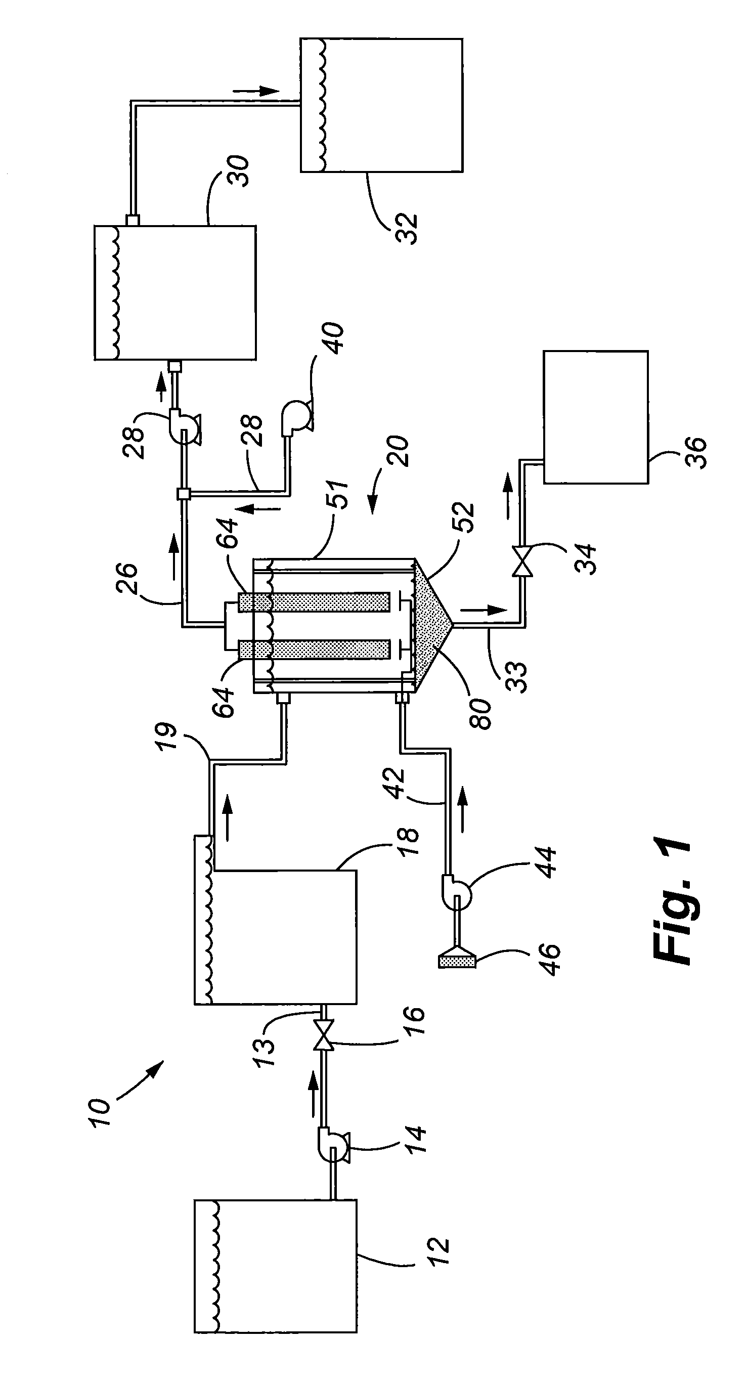
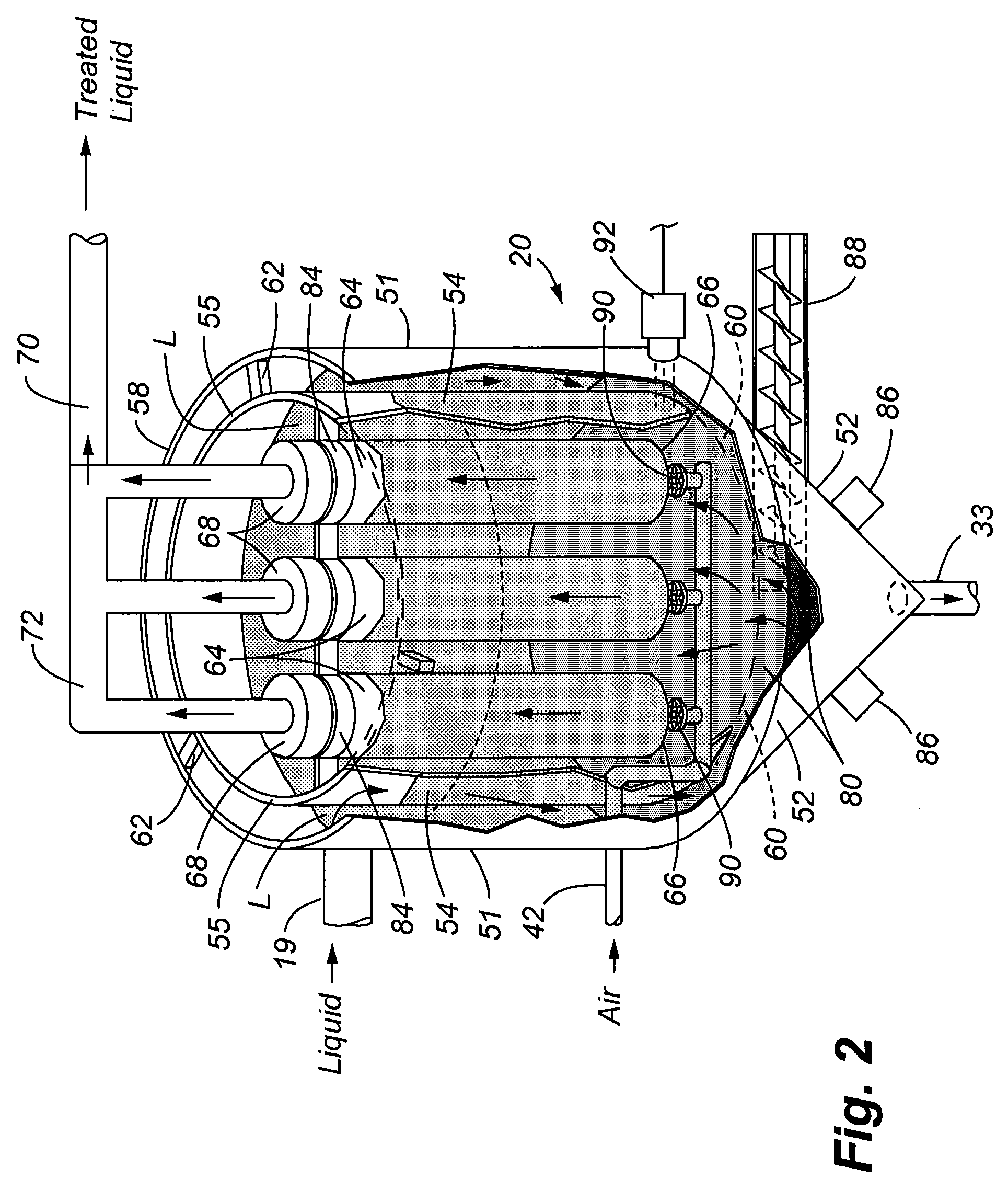
[0029]Referring to FIG. 1, a system 10 in accordance with the present invention is illustrated comprising a number of components that are used to provide treatment for the liquid, which may include water, or other liquids that are used in industrial and commercial purposes. The system 10 can be incorporated into yet a larger treatment system designed to specifically treat for removal of targeted contaminants. Thus, it shall be understood that the system 10 of the present invention can either be a stand-alone system, or can be incorporated within yet a larger treatment system.

[0030]FIG. 1 more specifically illustrates a first holding tank / reservoir 12 that provides the contaminated liquid to be treated. The liquid is conveyed to an electrocoagulation unit 18 by a pump 14 in which a control valve 16 regulates the flow of liquid through the conveying line 13. The electrocoagulation unit 18 may be conventional, such as the ones illustrated in the U.S. Pat. No. 7,211,185 entitled “METHOD...


PUM

PropertyMeasurementUnit
densityaaaaaaaaaa
vacuum forceaaaaaaaaaa
chemicalaaaaaaaaaa

Abstract

Methods and apparatuses for treatment of contaminated liquid are provided including an integrated ultra-filtration and clarification apparatus, and an optional integrated electrocoagulation capability. The integrated apparatus comprises an outer tank, an inner casing, and a plurality of ultra-filtration filters contained within the inner casing. Clarification of liquid occurs in the gap between the casing and tank. Solid matter settles, and aggregates in the bottom portion of the tank. The accumulated solid material acts as a secondary filter by pre-filtering the liquid prior to contact with the ultra-filtration filters. Clarified liquid is retained in a chamber of the casing, and the clarified liquid is drawn through the ultra-filtration filters as initiated by a source of vacuum communicating with the ultra-filtration filters. The integrated apparatus can be incorporated within any desired liquid treatment facility, and one combination in accordance with this system of the present invention includes an upstream electrocoagulation unit and a downstream reverse osmosis unit. The electrocoagulation function may be incorporated in the tank by a plurality of reaction plates or blades mounted to the interior sidewall of the tank. Additionally, the integrated apparatuses may include bacterial treatment in which a selected group of micro-organisms are introduced into the apparatus for treatment of particular contaminates.

Description

FIELD OF THE INVENTION[0001]The present invention relates generally to systems and methods for treating liquids to remove contaminates such as suspended or dissolved solids. More particularly, the present invention relates to a system and method for treatment of a contaminated liquid in which an integrated clarifier and ultra-filtration apparatus are provided to improve the overall treatment process prior to a final treatment action, such as filtration by reverse osmosis.BACKGROUND OF THE INVENTION[0002]Wastewater treatment is the process of removing targeted contaminants from a wastewater stream. Wastewater treatment typically involves a series of treatment steps including chemical, biological and physical treatment measures to remove the targeted contaminants. A typical wastewater treatment facility includes a number of physical components that operate in series to remove the targeted contaminants. The treatment components used in a wastewater treatment facility will differ depend...

Claims


Application Information

Patent Timeline
Patent Type & Authority Patents(United States)
IPC IPC(8): C02F3/00C02F1/463
CPCB01D61/16B01D61/145C02F3/102C02F9/005B01D61/18B01D61/025B01D2311/04B01D2311/2688B01D2315/06C02F1/441C02F1/444C02F1/463C02F2103/14C02F2209/42C02F2301/063B01D2311/2642Y02W10/10C02F9/20
Inventor POWELL, SCOTT W.
Owner POWELL SCOTT W
Why Eureka
Try Eureka