In-mold lamination of decorative products

a technology of decorative products and moulds, applied in the field of plastic composites, can solve the problems of high cost and limited durability, solutions that did not produce the look of luxury or the extended durability required in today's market, and achieve the effect of exceptional depth of image, luxurious appearance, and exceptional depth of imag

Inactive Publication Date: 2011-07-19
INT AUTOMOTIVE COMPONENTS GRP NORTH AMERICA INC
View PDF99 Cites 11 Cited by
  • Summary
  • Abstract
  • Description
  • Claims
  • Application Information

AI Technical Summary

Benefits of technology

[0022]Accordingly, it is an object of the present invention to provide a method of providing trim panels or appliqués having a wide variety of decorative patterns covered by an outer layer of injection molded clear plastic which provides an exceptional depth of image and luxurious appearance.
[0023]It is a further object of the present invention to provide appliqués and trim panels having an injection molded outer layer which provides an exceptional depth of image and luxurious appearance.
[0024]It is a still further object of the present invention to form appliqués and trim panels having a distinctive appearance wherein one or more of the injection molded or decorative layers include pigments, metallic flakes, tints, and / or reflective fibers which provide a unique color effect.
[0026]It is a further object of the present invention to form appliqués or trim panels having exceptional depth of image wherein the decorative layer is formed to final shape by the injection molding of the first, preferably clear, material against it.
[0027]It is a still further object of the present invention to provide a process for producing appliqués or trim panels having exceptional depth of image and decorative alternatives wherein such appliqués and panels are much thinner in cross-section than are presently available.

Problems solved by technology

Originally, real wood appliqués and finished metal panels were used, however, their popularity suffered due to their high cost and limited durability.
Subsequently, wood veneers and films with vacuum-deposited metal layers found favor, however, these solutions did not produce the look of luxury or the extended durability required in today's market.
The solvents used in such systems may cause undesirable environmental and emission problems.
Furthermore, the outer surface being a paint film may not exhibit an exceptional depth of image and may be readily scratched or abraded.
Such systems may require the use of expensive conventional coating systems and baking ovens to form a finish on the substrate that has the desired appearance.
However, the effort of forming the wooden veneer overlay to the desired shape is both time consuming and costly.
However, this reference does not disclose the use of a plastic backing layer.
While the various methods are suitable for their intended purpose, they all involve processing considerations that either produce emissions, require heavy capital investment in facilities or require unnecessary handling of one or more layers of material in the manufacture of a decorative exterior or interior trim product and do not produce an exceptional depth of image of the decorative layer.

Method used


Image

  • In-mold lamination of decorative products
  • In-mold lamination of decorative products
  • In-mold lamination of decorative products

Examples


example 1

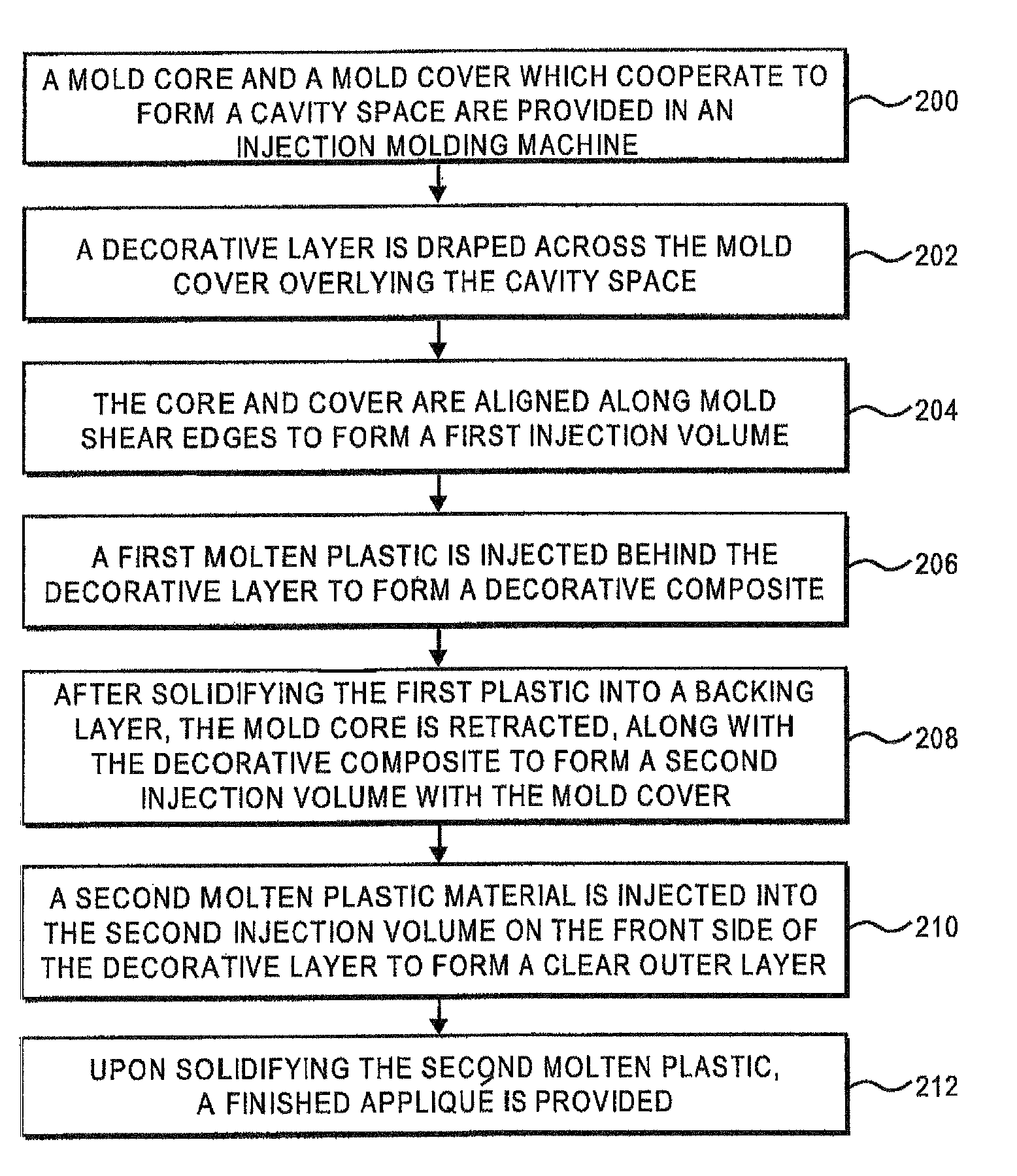
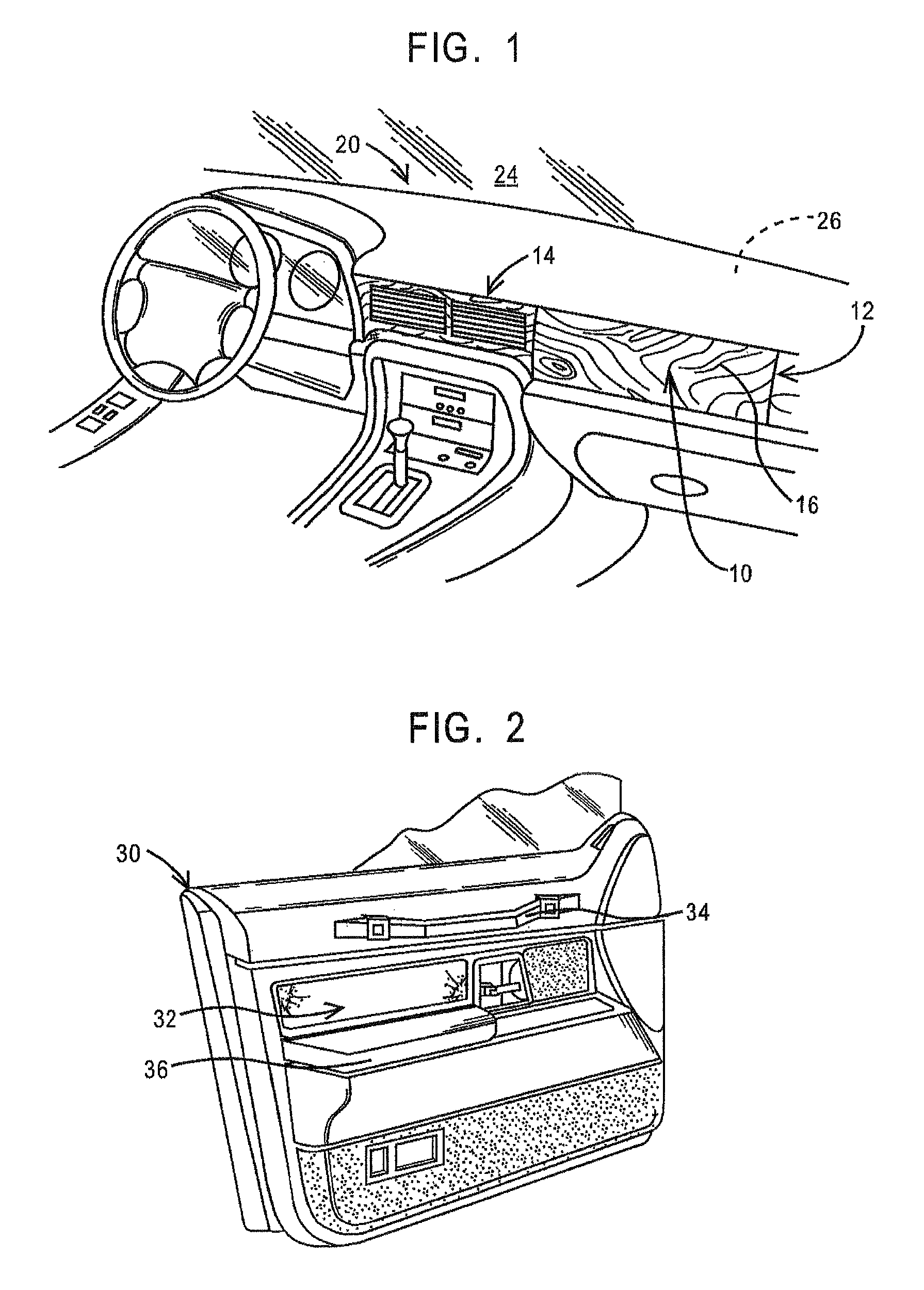
[0082]A thin wood veneer from Kimpara & Co., LTD. of Japan about 0.5 mm. in thickness was placed between the core and cover of an injection mold for an instrument panel appliqué such as shown in FIG. 1.

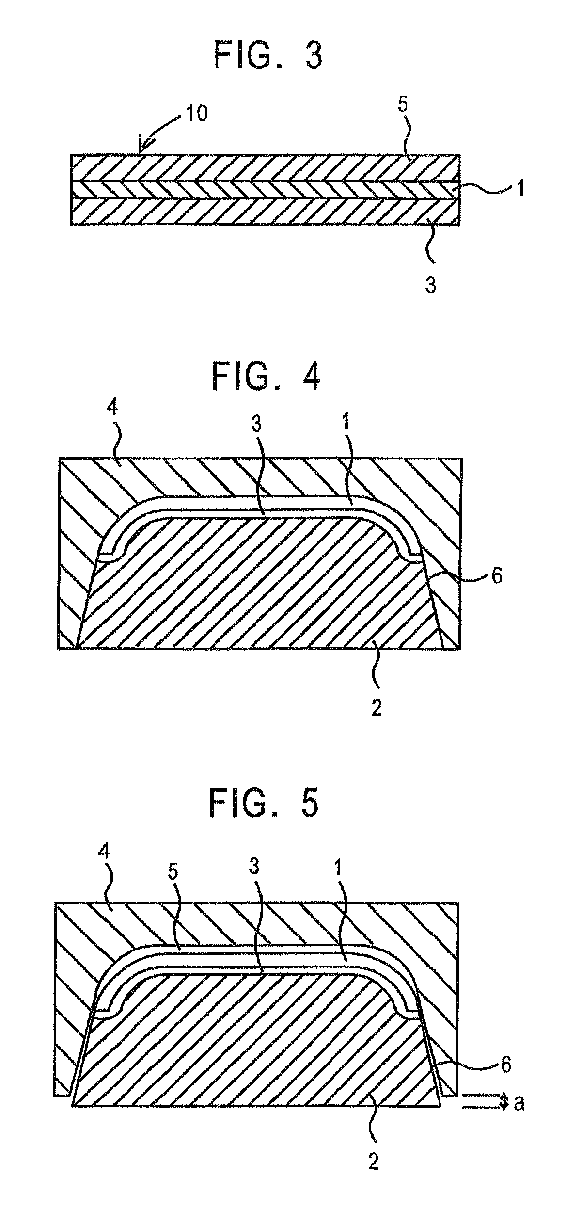
[0083]A first plastic material, 5135 polypropylene from Huntsman, LLC was injected behind the wood veneer layer to conform the layer to the shape of a contoured cavity area in the mold cover and fill out the cavity space to form a backing layer. After solidifying the backing layer the core portion of the mold set was retracted 1.5 mm with the backing layer and decorative layer composite remaining tightly affixed to the mold core. The resulting cavity space formed by the retraction of the core from the cover was filled with a second polymer material, V825 poly(methylmethacrylate) from the Atoglas Division of Atofina, the chemical branch of TOTAL. Upon cooling and demolding the appliqué, a wood grained molding having a luxurious appearance was obtained.

example 2

[0084]Using the same molding set up as in Example 1, a section of coarsely woven fabric, a circular knit, WF0023 from Collins and Aikman Products Co. was positioned between the mold core and mold cover. TOPAS® 6015S-04, a cyclic olefin copolymer from Ticona, was injected behind the fabric to shape it to the contoured cavity space in the mold cover and back the fabric with clear polymer. Upon cooling, the mold core was retracted along with the combined fabric and backing layer and a second layer of cyclic olefin copolymer was injected into the open space, thus forming a protective top layer on the fabric. Upon cooling and demolding, a unique appearing appliqué was formed having an open weave fabric appearance buried deep in a clear layer.

example 3

[0085]A relatively thin, at least partially transparent decorative film from Avery Dennison, about 0.5 mm. in thickness, was placed between the core and cavity of an injection mold. The film comprised an acrylic laminate having a pattern printed on one of the layers, the pattern covered by a second layer of acrylic such that over-molding would not disturb the appearance of the graphic pattern.

[0086]A clear plastic material, such as HFI-7 from Atoglas was injected on the front side of the decorative film to conform the film to the shape of the mold and fill out the space between the cover and core of the injection mold. This layer was about 1.5 mm. in thickness. The mold core was retracted to yield a cavity space between the back side of the decorative film and the mold core and that cavity space filled with a second layer of clear resin about 2.5 mm. in thickness. This composite was removed from the injection mold and a layer of paint applied to at least a portion of the backside of...


PUM

PropertyMeasurementUnit
thicknessaaaaaaaaaa
transparentaaaaaaaaaa
heataaaaaaaaaa

Abstract

A method of manufacturing decorative plastic composites having a decorative layer, a backing layer and a clear outer layer which provides exceptional “depth of image” is disclosed. Decorative or protective appliqués' having a wide range of decorative patterns may be formed by injection molding a backing layer behind and a clear outer layer on the top surface of a thin foil, film, fabric or veneer. A method is also disclosed for coating the exposed surface of the decorative layer between injection of the backing and outer layers to impart a desired visual effect or repair the surface. Use of multiple layers of decorative film, clear plastic and colored / opaque plastic is also disclosed to provide distinguishing visual effects.

Description

CROSS REFERENCE TO RELATED APPLICATIONS[0001]This application is a continuation-in-part of U.S. application Ser. No. 11 / 532,825 filed Sep. 18, 2006, which is a continuation-in-part of U.S. application Ser. No. 11 / 428,107 filed Jun. 30, 2006, which is a continuation of International Application No. PCT / US2005 / 000170 filed Jan. 3, 2005 and published Aug. 4, 2005 as International Publication No. WO 2005 / 070647, designating the United States, and which claims benefit of U.S. Provisional Application No. 60 / 533,632 filed Dec. 31, 2003, the teachings of which are incorporated herein by reference.FIELD OF THE INVENTION[0002]This invention relates to plastic composites formed by injection molding, particularly to plastic composites which find use as decorative appliqués for motor vehicle trim, and more particularly, to decorative appliqués having a wide variety of decorative patterns which exhibit exceptional “depth of image” provided by a layer of relatively clear plastic forming the outer ...

Claims


Application Information

Patent Timeline
Patent Type & Authority Patents(United States)
IPC IPC(8): B29C45/16
CPCB29C45/1671B32B27/08B32B5/022B32B5/024B32B15/08B32B21/08B32B21/14B32B27/10B32B27/12B32B27/20B32B27/286B32B27/302B32B27/304B32B27/308B32B27/325B32B27/36B32B27/365B32B27/40B32B3/02B32B3/08B32B2605/08B29L2031/3008B29L2031/3014B32B2250/03B32B2250/40B32B2307/4026B32B2307/41B32B2307/412B32B2307/416B32B2307/54B32B2307/71B32B2307/75B32B2479/00B32B2509/00B29C45/1679
Inventor HAYES, MARC A.NEITZKE, MARK K.CASS, MICHAEL W.
Owner INT AUTOMOTIVE COMPONENTS GRP NORTH AMERICA INC
Why Eureka
Try Eureka