In-Mold Lamination Of Decorative Products
- Summary
- Abstract
- Description
- Claims
- Application Information
AI Technical Summary
Benefits of technology
Problems solved by technology
Method used
Image
Examples
example 1
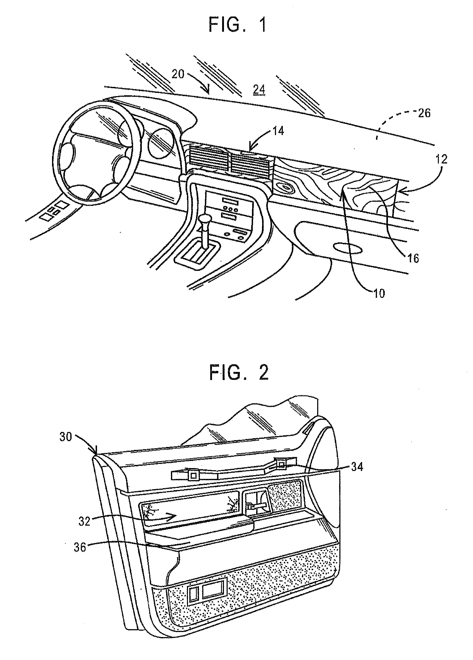
[0082]A thin wood veneer from Kimpara & Co., LTD. of Japan about 0.5 mm. in thickness was placed between the core and cover of an injection mold for an instrument panel appliqué such as shown in FIG. 1.
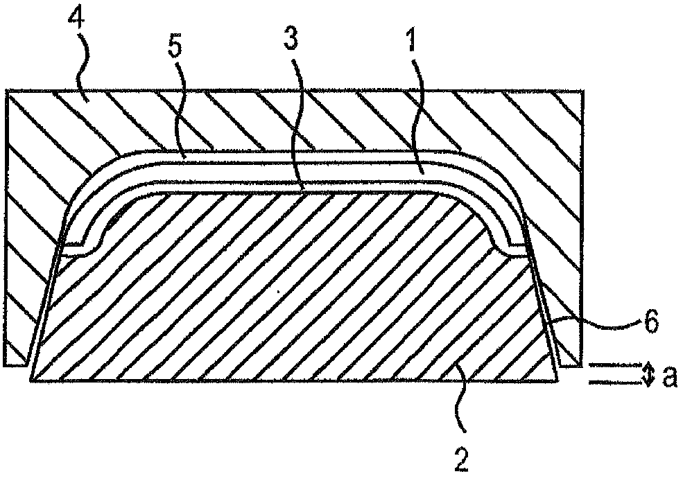
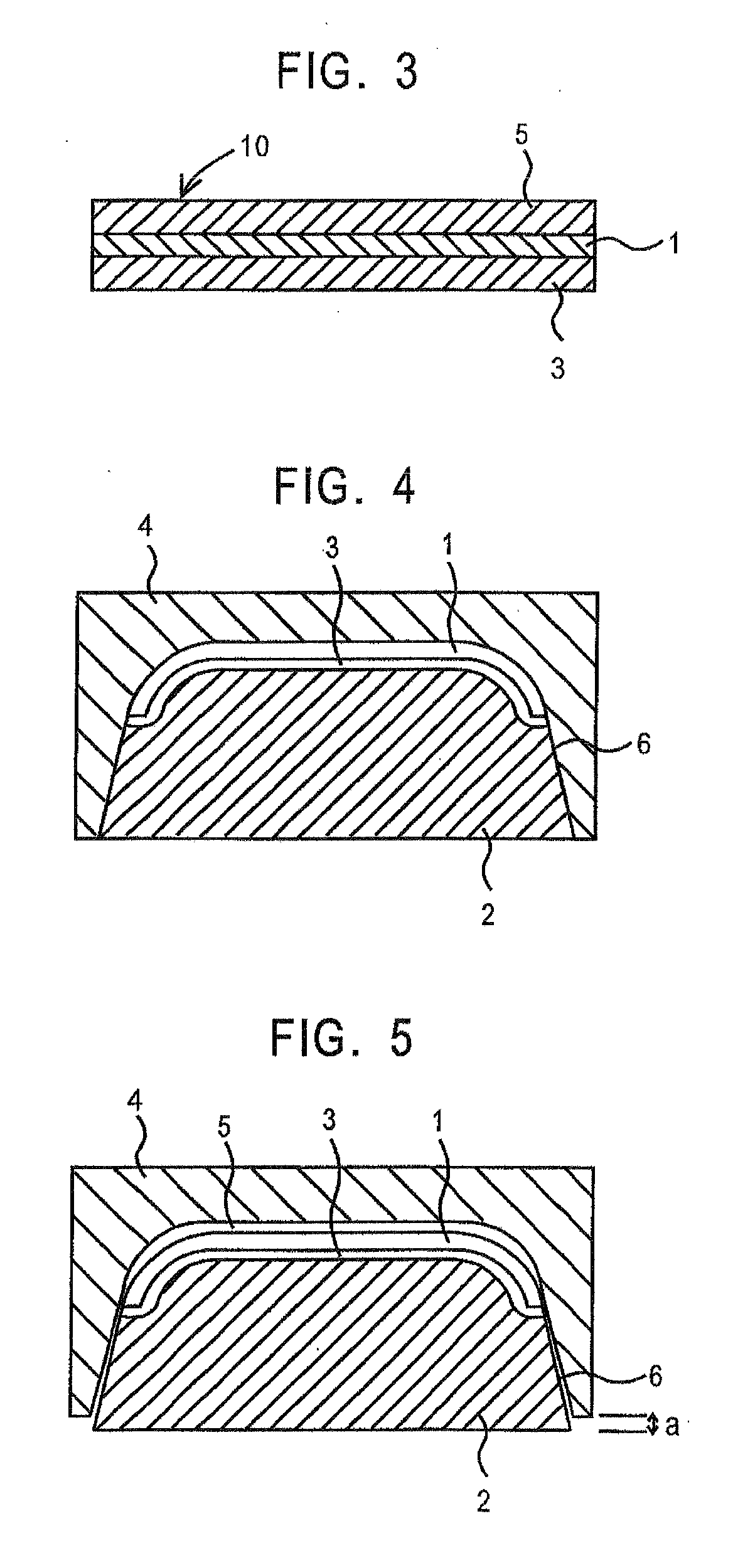
[0083]A first plastic material, 5135 polypropylene from Huntsman, LLC was injected behind the wood veneer layer to conform the layer to the shape of a contoured cavity area in the mold cover and fill out the cavity space to form a backing layer. After solidifying the backing layer the core portion of the mold set was retracted 1.5 mm with the backing layer and decorative layer composite remaining tightly affixed to the mold core. The resulting cavity space formed by the retraction of the core from the cover was filled with a second polymer material, V825 poly(methylmethacrylate) from the Atoglas Division of Atofina, the chemical branch of TOTAL. Upon cooling and demolding the appliqué, a wood grained molding having a luxurious appearance was obtained.
example 2
[0084]Using the same molding set up as in Example 1, a section of coarsely woven fabric, a circular knit, WF0023 from Collins and Aikman Products Co. was positioned between the mold core and mold cover. TOPAS® 6015S-04, a cyclic olefin copolymer from Ticona, was injected behind the fabric to shape it to the contoured cavity space in the mold cover and back the fabric with clear polymer. Upon cooling, the mold core was retracted along with the combined fabric and backing layer and a second layer of cyclic olefin copolymer was injected into the open space, thus forming a protective top layer on the fabric. Upon cooling and demolding, a unique appearing appliqué was formed having an open weave fabric appearance buried deep in a clear layer.
example 3
[0085]A relatively thin, at least partially transparent decorative film from Avery Dennison, about 0.5 mm. in thickness, was placed between the core and cavity of an injection mold. The film comprised an acrylic laminate having a pattern printed on one of the layers, the pattern covered by a second layer of acrylic such that over-molding would not disturb the appearance of the graphic pattern.
[0086]A clear plastic material, such as HFI-7 from Atoglas was injected on the front side of the decorative film to conform the film to the shape of the mold and fill out the space between the cover and core of the injection mold. This layer was about 1.5 mm. in thickness. The mold core was retracted to yield a cavity space between the back side of the decorative film and the mold core and that cavity space filled with a second layer of clear resin about 2.5 mm. in thickness. This composite was removed from the injection mold and a layer of paint applied to at least a portion of the backside of...
PUM
| Property | Measurement | Unit |
|---|---|---|
| Transparency | aaaaa | aaaaa |
| Plasticity | aaaaa | aaaaa |
| Heat | aaaaa | aaaaa |
Abstract
Description
Claims
Application Information
 - R&D
- Intellectual Property
- Life Sciences
- Materials
- Tech Scout
- Unparalleled Data Quality
- Higher Quality Content
- 60% Fewer Hallucinations
Browse by: Latest US Patents, China's latest patents, Technical Efficacy Thesaurus, Application Domain, Technology Topic, Popular Technical Reports.
© 2025 PatSnap. All rights reserved.Legal|Privacy policy|Modern Slavery Act Transparency Statement|Sitemap|About US| Contact US: help@patsnap.com


