
Radar calibration structure and method

a technology of applied in the field ofradar calibration structure and method, can solve the problems of limited antenna beam slew rate, physical limitations to the amount of power that can be generated practically or economically, and cannot ordinarily be modified by the beam shap

Inactive Publication Date: 2011-07-19
LOCKHEED MARTIN CORP
View PDF1 Cites 29 Cited by
  • Summary
  • Abstract
  • Description
  • Claims
  • Application Information

AI Technical Summary

Problems solved by technology

Such systems are limited in their antenna beam slew rate by the inertia of the moving reflector, and are not ordinarily capable of modifying the beam shape without modification to the shape of the reflector.
However, there are physical limitations to the amount of power that can practically or economically be generated.
While distribution of low-power excitation ameliorates unwanted leakage from the exciter to the receiver, the problem remains of causing the beam direction and shape to assume the desired configuration.
The large number of signal paths in a large array antenna makes precalibration of the amplitude and phase of all of the paths difficult and expensive, and the characteristics of the paths may change after they are calibrated due to environmental effects, damage or even simple aging.
Leakage paths of the characterization signal into unintended signal paths cause errors in the calibration.

Method used


Image

  • Radar calibration structure and method
  • Radar calibration structure and method
  • Radar calibration structure and method

Examples


Embodiment Construction

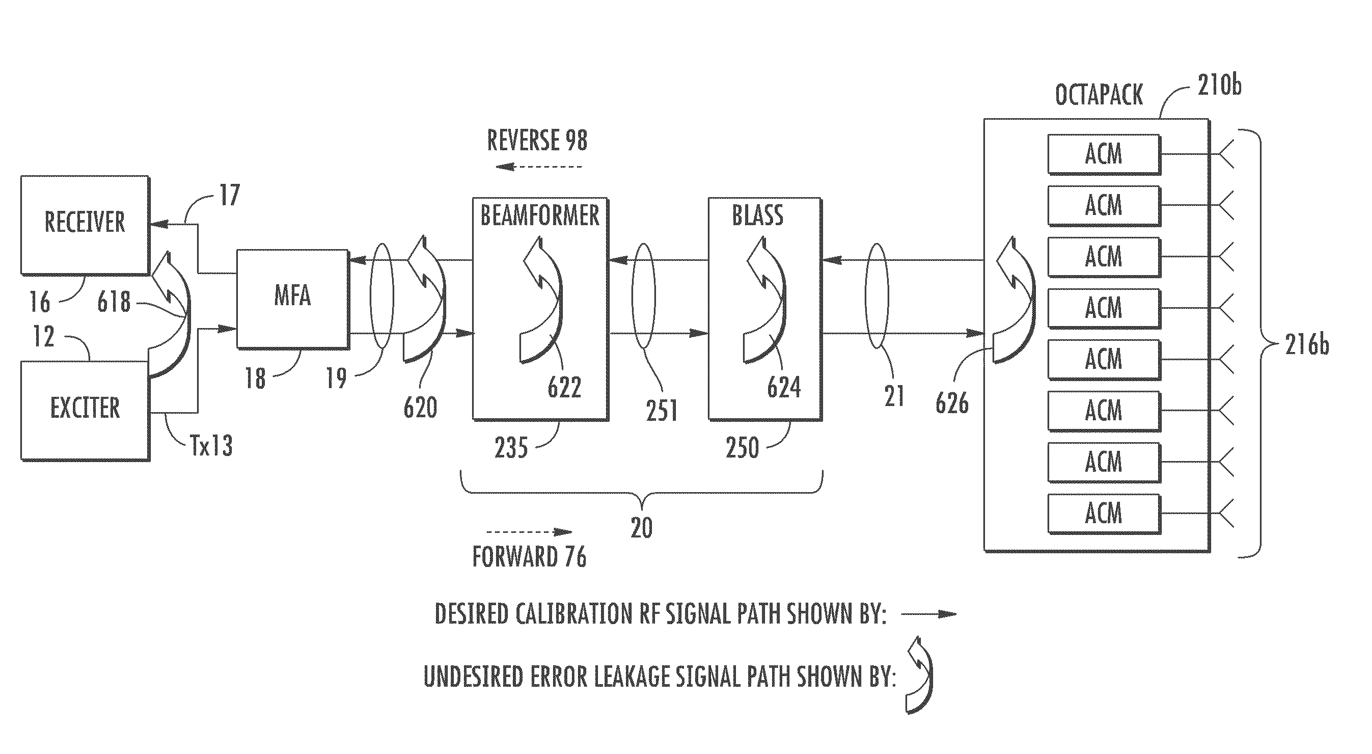
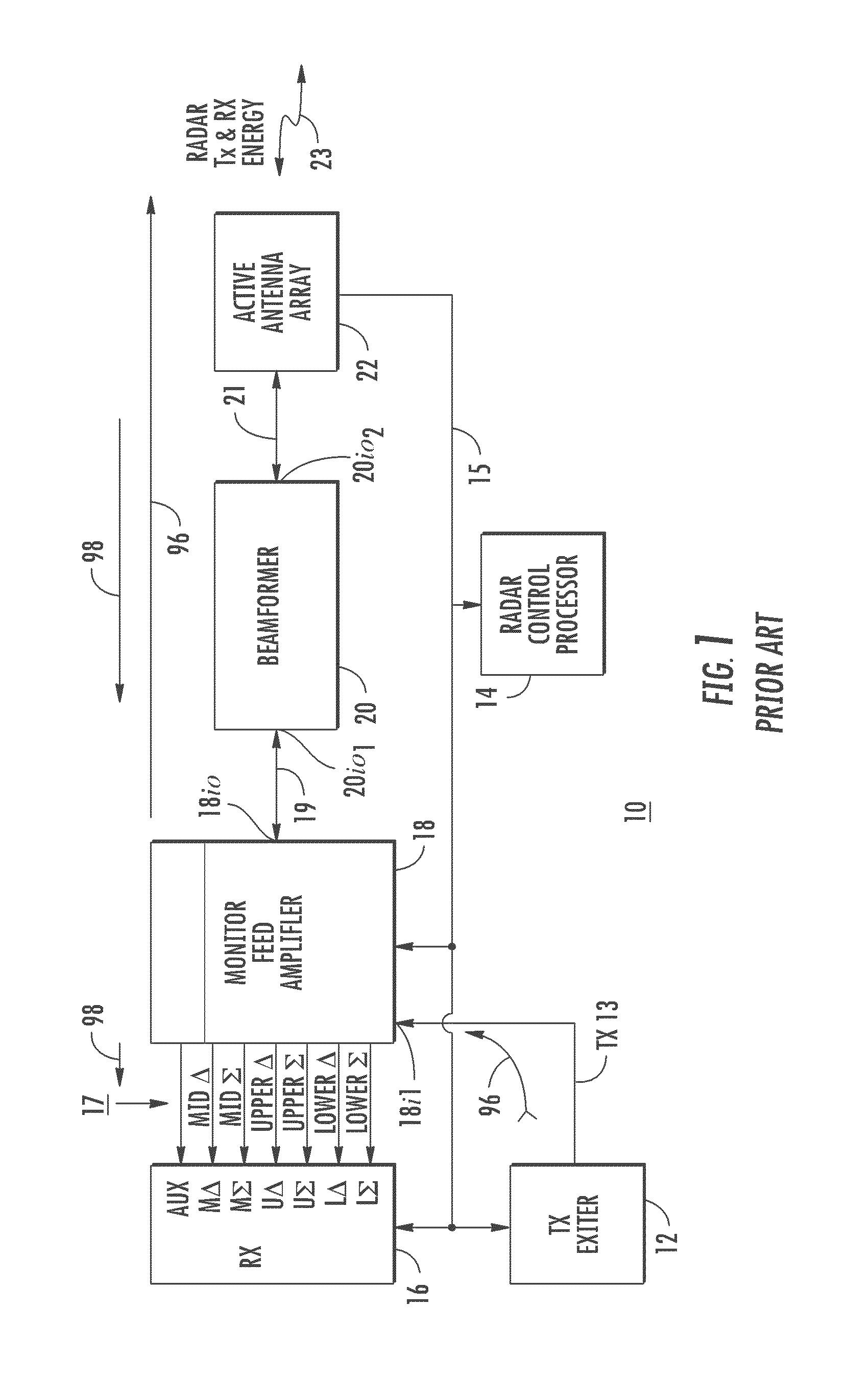
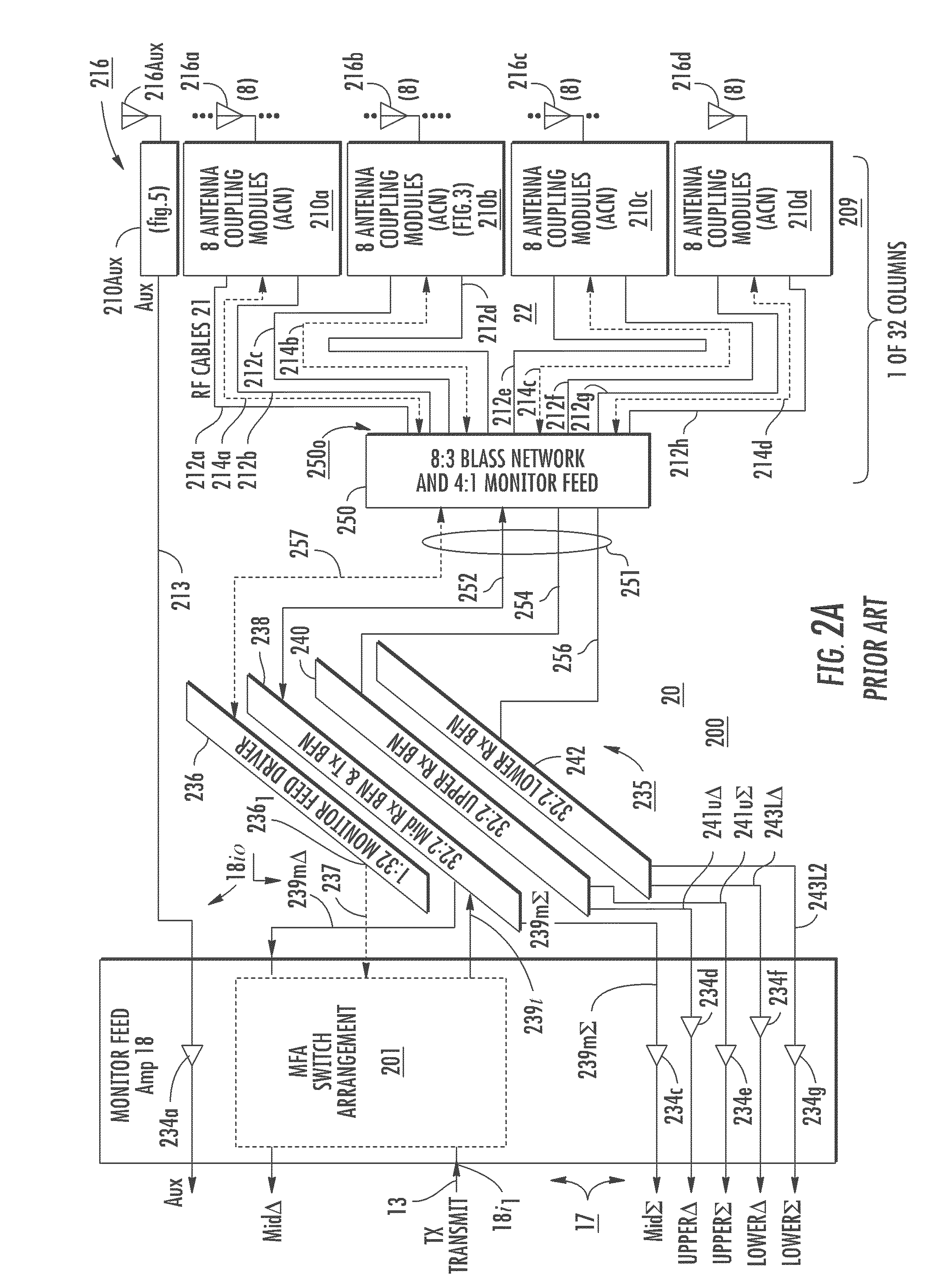
[0036]FIG. 6 is a simplified or notional representation of the desired calibration paths and undesired leakage paths in the radar system of FIG. 1. Elements of FIG. 6 corresponding to those of FIGS. 1 and 2 are designated by like reference numerals. In FIG. 6, the desired calibration signal paths are indicated by straight solid-line arrows, and undesired signal leakage paths by curled arrows. Directional arrows 96 and 98 are dashed. More particularly, the desired calibration signal paths include, starting from the exciter 12, the path 13, the MFA 18, path 19, beamformer portion 235, paths 251, Blass portion 250, and paths 21 to the antenna coupling networks of the one illustrated octapack 210b. That is to say, that in order to characterize each of the forward paths 96 (from exciter toward antennas) and reverse paths 98 (from antennas toward receiver), excitation signal is transmitted through the forward paths, coupled to a return path in an antenna coupling element, and returned to ...


PUM


Abstract

A radar system with an array antenna includes various signal paths, including beamformers, extending between an exciter, a receiver, and the array antenna. The signal paths are calibrated by a method that includes frequency modulation of the exciter signals that reach the “antenna” and additional amplitude modulation of signals just as they enter the receiver. Leakage paths directly from the exciter to the receiver are unmodulated, those extending from the exciter through the beamformer are amplitude modulated, and only those reaching the “antenna” and returning to the receiver are both amplitude and frequency modulated. The receiver is tuned to receive only the “doubly-modulated” signals, which tends to reject leakage signals.

Description

GOVERNMENT RIGHTS[0001]This invention was made with Government Support under Contract No. W15P7T-06-C-T004 (Eq36) awarded by the Department of the Army. The Government has certain rights in this invention.BACKGROUND OF THE INVENTION[0002]Radar systems using shaped reflectors to form the beams have been in use for more than 50 years. In such radar systems, a high power transmitter is connected to a port of the reflector antenna, for transmitting a radar beam. Such systems are limited in their antenna beam slew rate by the inertia of the moving reflector, and are not ordinarily capable of modifying the beam shape without modification to the shape of the reflector. Modern radar systems are required to quasi-simultaneously generate plural radar antenna beams pointing in disparate directions, and for this reason tend to use phased-array antennas rather than reflector-type antennas. In a traditional phased-array antenna arrangement, the transmit signal is coupled from a single source or e...

Claims


Application Information

Patent Timeline
Patent Type & Authority Patents(United States)
IPC IPC(8): G01S7/40
CPCG01S7/4004H01Q3/267
Inventor USCINOWICZ, MICHAEL B.
Owner LOCKHEED MARTIN CORP
Learn More