SBI motion artifact removal apparatus and method

a motion artifact and motion technology, applied in the field of sbi motion artifact removal apparatus and method, can solve the problems that the human visual system cannot resolve high resolution in a moving scene, and the user only requires resolution sufficient, so as to reduce the resolution of the image, reduce the occurrence of motion artifacts and tearing, and reduce the occurrence of tearing effects and other visual artifacts.

Inactive Publication Date: 2011-07-19
ETHICON ENDO SURGERY INC
View PDF401 Cites 617 Cited by
  • Summary
  • Abstract
  • Description
  • Claims
  • Application Information

AI Technical Summary

Benefits of technology

[0009]Recognizing that users of SBI devices do not always need to see the subject matter at the highest possible resolution at all times, one embodiment of the system, device and method couples the resolution of the SBI device inversely to the motion of the SBI device and subject matter being imaged. When the SBI device is not moving relative to the subject matter, the maximum resolution is presented for optimal viewing by the user. When the SBI device moves appreciably relative to the subject matter, the resolution of the image is decreased, thereby reducing the occurrence of tearing effects and other visual artifacts that would otherwise be perceived by the user. Altering the displayed resolution is accomplished using a motion artifact removal image processor.
[0010]Small rapid movements can continue to occur even with the steadiest of hands. This can occur during periods when high resolution is desired by the user and therefore an alternative strategy is employed. This embodiment of the invention tracks the motion of the SBI device and associates one or more vectors with each data sample. The motion artifact removal image processor then reconstructs a corrected image from the SBI image stream by using one or more of the vectors to translate each data sample to the proper position relative to the other data samples as if there had been no motion. Reconstruction of the image presents the user a corrected image with reduced motion artifacts and tearing while maintaining the native high resolution of the SBI imager as much as possible.

Problems solved by technology

It is well known that the human visual system cannot resolve high resolution in a moving scene.
Therefore, the user only requires resolution sufficient to see larger structures to help guide the user to the area desired to be imaged.

Method used


Image

  • SBI motion artifact removal apparatus and method
  • SBI motion artifact removal apparatus and method
  • SBI motion artifact removal apparatus and method

Examples


Embodiment Construction

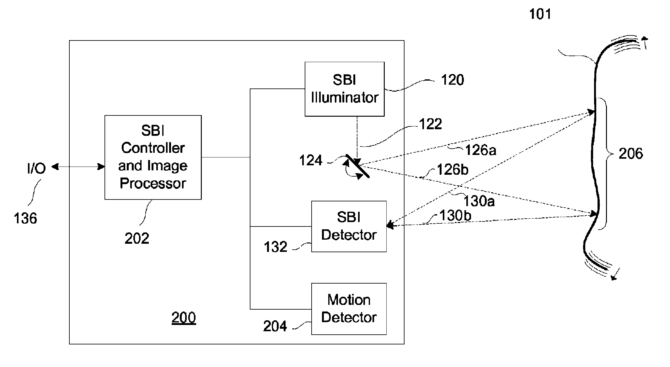
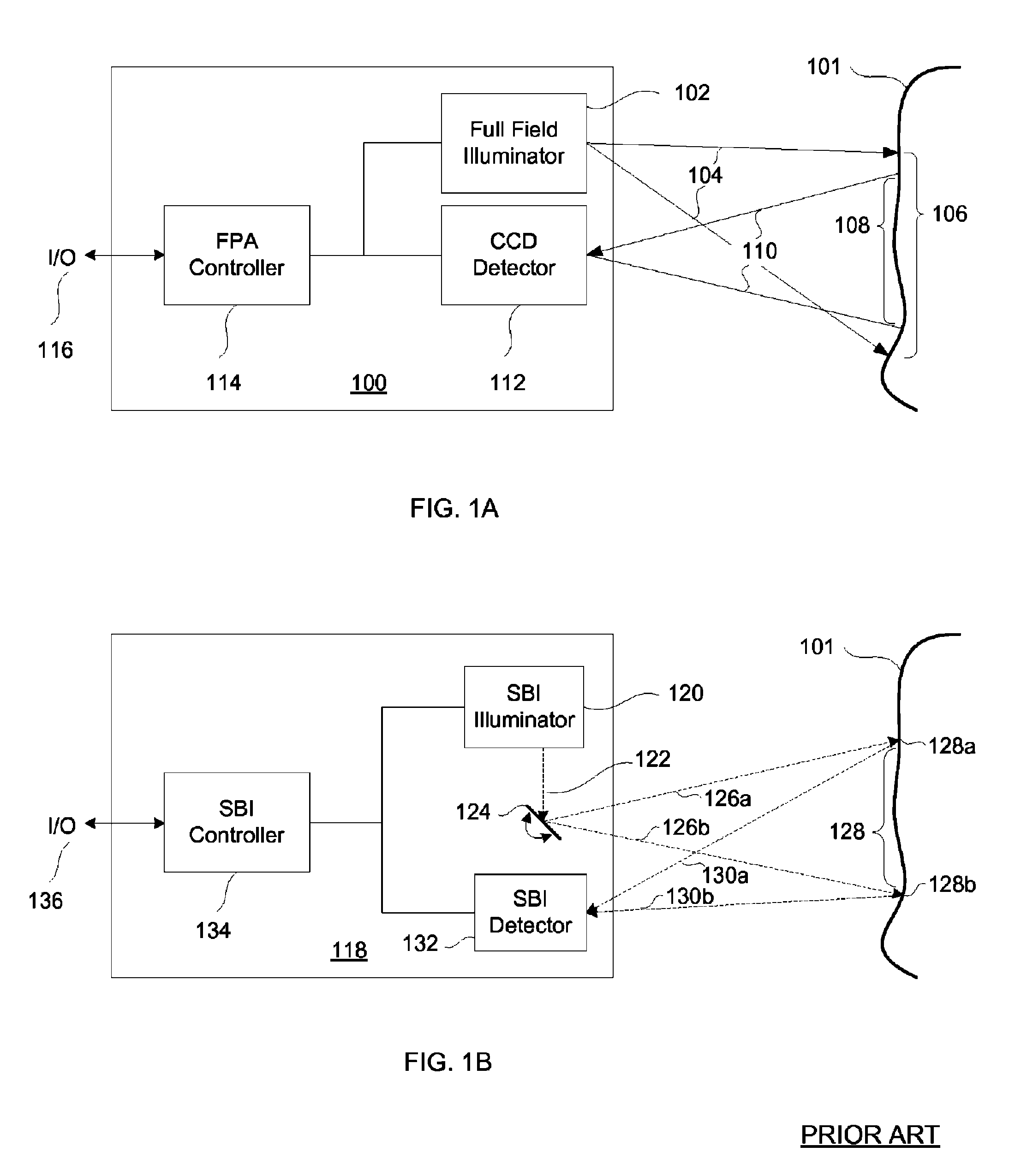
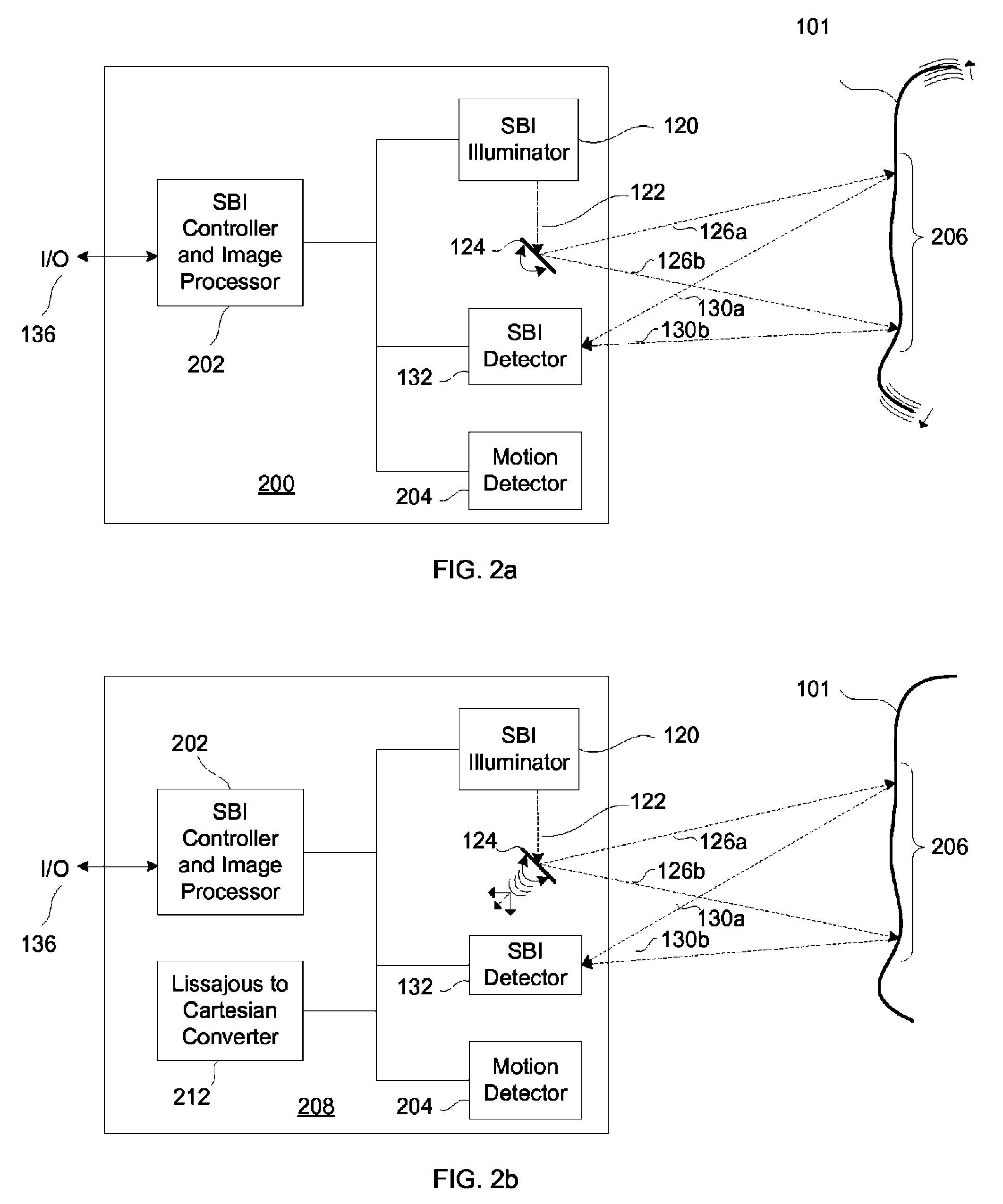
[0021]FIGS. 1a and 1b detail the prior art imaging systems. FIGS. 2a and 2b describe exemplary embodiments of the present invention. FIGS. 3a and 3b illustrate the scanning and data sample translation processes of an SBI device and system. FIGS. 4a-c, and 5 show examples of the artifact removal processes.

Prior Art FPA Imaging System

[0022]Referring now to the schematic diagram of a prior art FPA imaging system 100 depicted in FIG. 1a, the FPA controller 114 controls an I / O port 116, a full field illuminator 102, and a CCD detector 112. The full field illuminator 102 illuminates a target illumination area 106 of a target subject matter 101 with a broad beam of illumination 104. The CCD detector 112 spatially resolves returned illumination 110 from the target imaging area 108 and converts it to an electrical signal for eventual display.

[0023]In a typical prior art FPA imaging system 100, a full field illuminator 102 illuminates a target illumination area 106 of a target subject matter ...


PUM


Abstract

A system, method and apparatus for eliminating image tearing effects and other visual artifacts perceived when scanning moving subject matter with a scanned beam imaging device. The system, method and apparatus uses a motion detection means in conjunction with an image processor to alter the native image to one without image tearing or other visual artifacts. The image processor monitors the motion detection means and reduces the image resolution or translates portions of the imaged subject matter in response to the detected motion.

Description

TECHNICAL FIELD[0001]The present invention relates generally to systems, devices, and methods for eliminating image tearing effects and other visual artifacts perceived during imaging when an SBI or Scanned Beam Imaging device moves appreciably relative to the subject matter being imaged.BACKGROUND OF THE INVENTION[0002]Imaging devices can have different native resolutions and frame rates. Focal Plane Array (FPA) devices typically use Charge Coupled Device (CCD) or similar technologies to capture video images. CCD imagers typically capture 30 full frames per second (fps) using a technique called interlacing, whereby first the odd numbered horizontal lines of the frame are imaged and then the even numbered lines are imaged. Each half frame is resolved all at once at 60 fps, and when displayed on a screen each half frame is blended to some degree by the human eye with the next half frame to make the full screen image. The 60 fps refresh rate is generally beyond the human perception th...

Claims


Application Information

Patent Timeline
Patent Type & Authority Patents(United States)
IPC IPC(8): H04N5/228H04N5/217H01J5/16A61B1/06A61B6/00H04N5/335
CPCG06T7/20G06T5/003G02B26/101G06T2207/20201
Inventor DUNKI-JACOBS, ROBERT J.WEIR, MICHAEL P.
Owner ETHICON ENDO SURGERY INC
Why Eureka
Try Eureka