
Developing member with urethane resin and silicone surface layer

a technology of silicone surface layer and developing member, which is applied in the direction of instruments, electrographic process apparatus, optics, etc., can solve the problems of large friction, high tackiness, and non-uniformity of triboelectric charge quantity, and achieve the effect of lessening the occurring of banding

Active Publication Date: 2011-07-19
CANON KK
View PDF14 Cites 2 Cited by
  • Summary
  • Abstract
  • Description
  • Claims
  • Application Information

AI Technical Summary

Benefits of technology

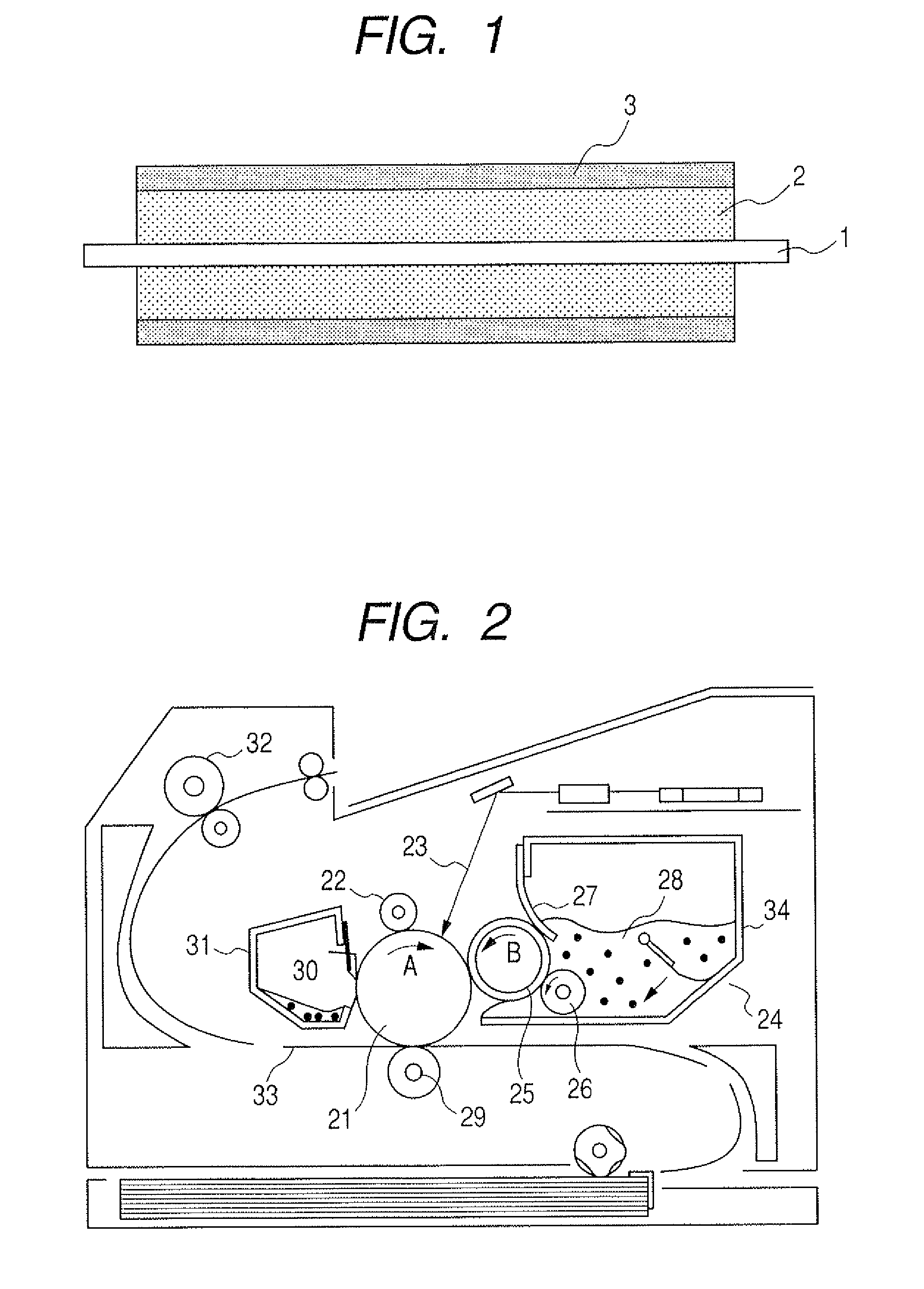
The present invention provides a developing roller that can reduce the occurrence of banding in electrophotographic images caused by the exudation of components from the developer feed roller. The developing roller and the developer feed roller have been brought into contact with each other in the quiescent condition. The invention also provides a developing assembly that can reduce faulty electrophotographic images caused by the exudates out of the developer feed roller. The invention further provides an electrophotographic image forming apparatus enabling high-grade electrophotographic image formation. The invention is achieved by using a urethane resin layer containing a silicone compound having a polyether moiety consisting of an ether repeating unit whose total number of carbon atoms ranges from 3 to 9.

Problems solved by technology

Japanese Patent Application Laid-open No. 2003-167398 discloses that a urethane resin is preferable as a material for forming a surface layer of a conductive member used in the developing assembly of the electrophotographic image forming apparatus, but on the other hand has disadvantageous properties that it has a high tackiness and also may cause a large friction.
Also, it follows that these continue to come into contact with each other at the same position over a long period time when the electrophotographic apparatus is continuously kept to stand unoperated over a long period time.
In other words, the triboelectric charge quantity comes non-uniform.

Method used


Image

  • Developing member with urethane resin and silicone surface layer
  • Developing member with urethane resin and silicone surface layer
  • Developing member with urethane resin and silicone surface layer

Examples


example 1

[0133]Formation of Conductive Elastic Layer:

[0134]A mandrel (shaft member) of 8 mm in outer diameter was placed in a cylindrical mold of 16 mm in inner diameter in such a way that these came concentric with each other. As a material for forming an elastic layer, liquid conductive silicone rubber (available from Dow Corning Toray Silicone Co., Ltd.; Asker-C hardness: 40 degrees; volume resistivity: 1×10⁷ Ωcm) was casted into the mold. After casting, this was put into an oven of temperature 130° C. to carry out heat-molding for 20 minutes. The molded product obtained was demolded, and thereafter secondarily vulcanized for 4 hours in an oven of temperature 200° C. to form a conductive elastic layer of 4 mm in thickness on the shaft member.

[0135]Preparation of Resin Layer Forming Coating Material:

[0136]The following components (a1) and (a2) were stepwise mixed in a methyl ethyl ketone solvent to carry out reaction at 80° C. for 3 hours in an atmosphere of nitrogen to obtain a bifunction...

example 2

[0146]A developing roller was produced in the same manner as that in Example 1 except that 5 parts by mass of the non-reactive silicone compound (Silicone Compound 1) used in the resin layer forming coating material was changed for 0.08 part by mass of a non-reactive silicone compound (Silicone Compound 2).

example 3

[0147]A developing roller was produced in the same manner as that in Example 1 except that 5 parts by mass of the non-reactive silicone compound (Silicone Compound 1) used in the resin layer forming coating material was changed for 0.1 part by mass of a non-reactive silicone compound (Silicone Compound 4).


PUM


Abstract

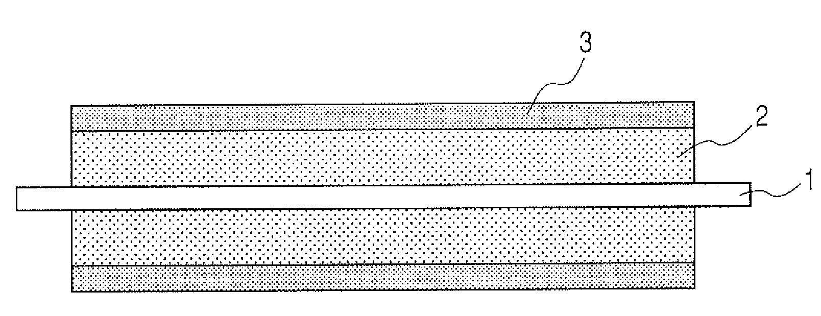
A developing member is disclosed which can lessen the occurring of banding. The developing member has a shaft member, an elastic layer provided on the shaft member, and a resin layer provided on the surface, wherein the resin layer contains a urethane resin and a non-reactive silicone compound, and the non-reactive silicone compound has a polyether moiety whose total number of carbon atoms ranges from 3 to 9.

Description

BACKGROUND OF THE INVENTION[0001]1. Field of the Invention[0002]This invention relates to a developing member such as a developing roller used in, e.g., electrophotographic image forming apparatus such as copying machines and laser beam printers, and also relates to a developing assembly and an image forming apparatus which make use of the developing member.[0003]2. Description of the Related Art[0004]As one of development processes used in electrophotographic apparatus such as copying machines, laser beam printers, and receiving sets of facsimile machines, a pressure development process is available in which a non-magnetic toner-component developer is used and the developer is made to adhere to an electrostatic latent image held on a photosensitive drum, to render the latent image visible. This pressure development process is widely used because it requires no magnetic material, facilitates manufacture of simple and compact apparatus, and also facilitates preparation of color devel...

Claims


Application Information

Patent Timeline
Patent Type & Authority Patents(United States)
IPC IPC(8): G03G15/08
CPCG03G15/0818G03G2215/0634G03G2215/0861G03G15/06G03G5/02
Inventor NAKAMURA, MINORUKASHIWABARA, RYOTATANAKA, ATSUSHI
Owner CANON KK
Learn More