Plasma flow controlled diffuser system

a technology of diffuser and plasma flow, which is applied in the direction of machines/engines, liquid fuel engines, lighting and heating apparatus, etc., can solve the problems of large pre-diffusers, difficult to implement such additional diffusers, or pre-diffusers, in connection with compressors for gas turbine engines, and undesirable increase in length and/or weight of engines

Active Publication Date: 2011-07-26
HONEYWELL INT INC
View PDF28 Cites 33 Cited by
  • Summary
  • Abstract
  • Description
  • Claims
  • Application Information

AI Technical Summary

Problems solved by technology

However, to date, it has been difficult to implement such additional diffusers, or pre-diffusers, in connection with compressors for gas turbine engines, for example those with axial compressors and / or in-line combustors.
For example, such pre-diffusers have generally been significantly large.
As a result, any placement of such a pre-diffuser in a centrifugal compressor could generally result in an undesirable increase in the length and / or weight of the engine.
In addition, control of air flow through such pre-diffusers can also be difficult.

Method used


Image

  • Plasma flow controlled diffuser system
  • Plasma flow controlled diffuser system
  • Plasma flow controlled diffuser system

Examples


Embodiment Construction

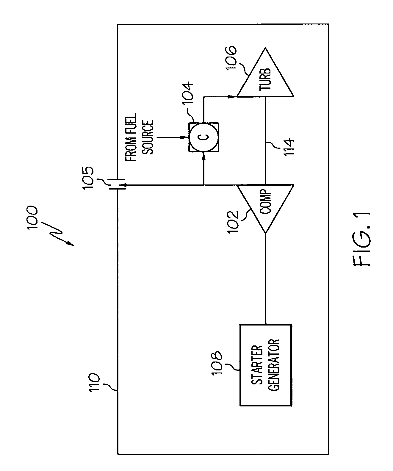
[0017]FIG. 1 depicts an embodiment of an exemplary gas turbine engine 100 in a simplified cross-sectional format. In a preferred embodiment, the gas turbine engine 100 is part of a propulsion system for an aircraft. However, this may vary in other embodiments. The gas turbine engine 100 includes a compressor 102, a combustor 104, a turbine 106, and a starter-generator unit 108, all preferably housed within a single containment housing 110.

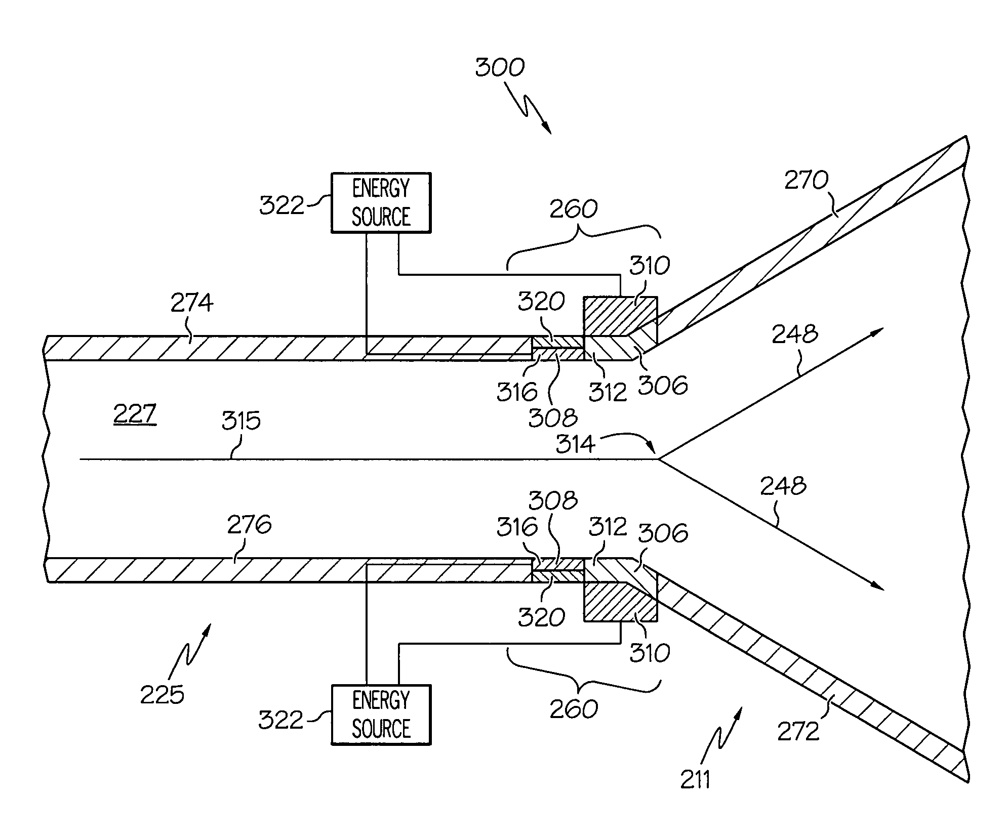
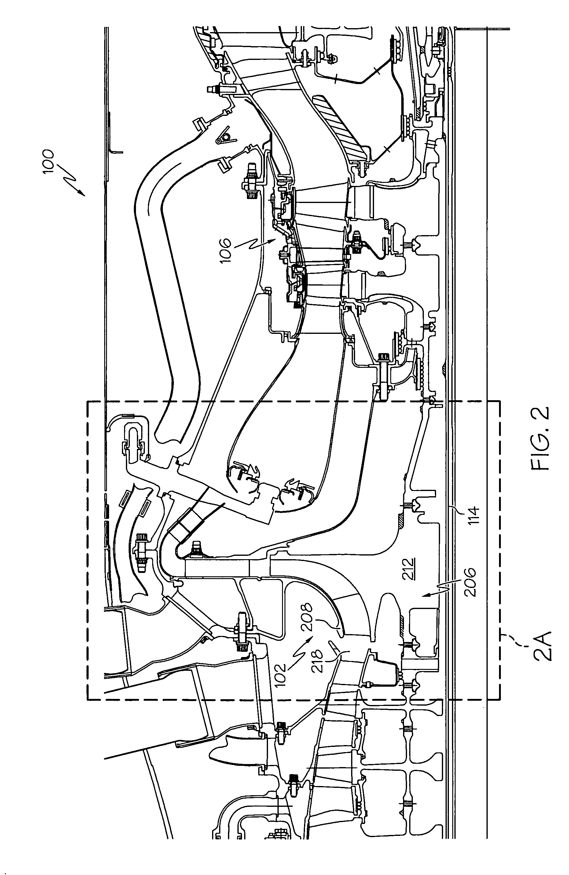
[0018]The compressor 102 is formed within the housing 110, and is configured to supply compressed air to the combustor 104. In a preferred embodiment depicted in FIGS. 2 and 2A and described further below in connection therewith, the compressor 102 comprises an impeller, a first diffuser, and a second diffuser.

[0019]During operation of the gas turbine engine 100, the compressor 102 draws ambient air into the housing 110. The compressor 102 compresses the ambient air, and supplies a portion of the compressed air to the combustor 104, and may also su...


PUM


Abstract

A diffuser system for a compressor for a gas turbine engine includes a diffuser and a plasma actuator. The diffuser comprises a first wall and a second wall. The first and second walls form a diffuser flow passage therebetween. The plasma actuator is disposed at least partially proximate the second wall. The plasma actuator is adapted to generate an electric field to ionize a portion of air flowing through the flow passage.

Description

TECHNICAL FIELD[0001]The present invention relates to gas turbine engines, and more particularly relates to diffusers for gas turbine engines.BACKGROUND[0002]Aircraft main engines not only provide propulsion for the aircraft, but in many instances may also be used to drive various other rotating components such as, for example, generators, compressors, and pumps, to thereby supply electrical, pneumatic, and / or hydraulic power. Generally, a gas turbine engine includes a combustor, a power turbine, and a compressor. During operation of the engine, the compressor draws in ambient air, compresses it, and supplies compressed air to the combustor. The compressor also typically includes a diffuser that diffuses the compressed air before it is supplied to the combustor. The combustor receives fuel from a fuel source and the compressed air from the compressor, and supplies high energy compressed air to the power turbine, causing it to rotate. The power turbine includes a shaft that may be us...

Claims


Application Information

Patent Timeline
Patent Type & Authority Patents(United States)
IPC IPC(8): F02C1/00
CPCF23C99/001F04D29/687F04D29/441F23R3/04F23L2900/00001Y02T50/675Y02T50/60
Inventor NOLCHEFF, NICK
Owner HONEYWELL INT INC
Why Eureka
Try Eureka