
Seat height adjusting device for automobile

a technology for automobile seats and heights, which is applied in the direction of movable seats, vehicle components, vehicle arrangement, etc., can solve the problems of difficult to determine the positional relationship between the parts around the side frame and the side frame, the deformation and/or damage and the deformation of the side frame and/or the portion of the upper rail member which is strongly abutted against each other, etc., to achieve the effect of facilitating the prevention of the side fram

Inactive Publication Date: 2011-07-26
TS TECH CO LTD
View PDF12 Cites 22 Cited by
  • Summary
  • Abstract
  • Description
  • Claims
  • Application Information

AI Technical Summary

Benefits of technology

The present invention provides a seat height adjusting device for automobiles that can prevent damage to the seat and position sensors, as well as simplifying the construction and reducing the number of support pins. The device includes a linkage base frame that can be vertically swung, an operating knob for adjusting the frame, and power transmission means for smoothly and stably adjusting the seat. The device also includes a stopper means to prevent the seat from being lowered too far. The invention also provides a slide rail mechanism and a position sensor system for accurate adjustment of the seat position.

Problems solved by technology

As a result, portions of the side frames 2 and portions of the upper rail members A which are strongly abutted against each other are deformed and / or damaged.
Moreover, in a case where the height adjusting device is applied to a slide-type automobile seat with a position sensor system, in which position sensors, electrical wirings thereof and / or the like (any automotive electronic parts and / or the like) are arranged on upper surfaces of upper rail members of a slide rail mechanism or arranged in the vicinity of the upper rail members, when the occupant on the seat operates the operating knob in such a manner that the seat is excessively lowered, or any excessive load is applied to the seat in a condition where the seat has been in a lowermost position, side frames of the seat are abutted against the position sensors, the electrical wirings and / or the like, to thereby cause them to be damaged.
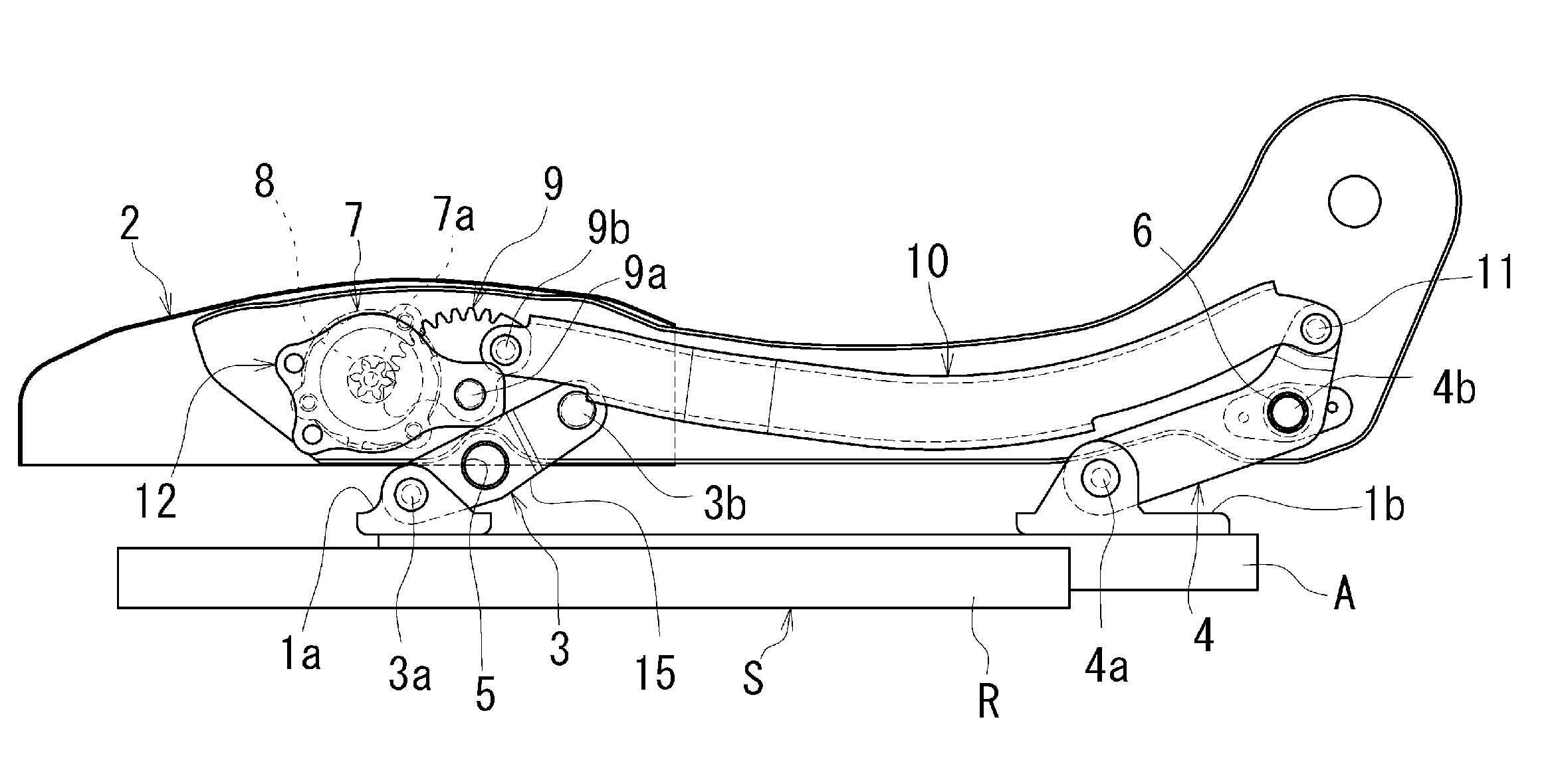
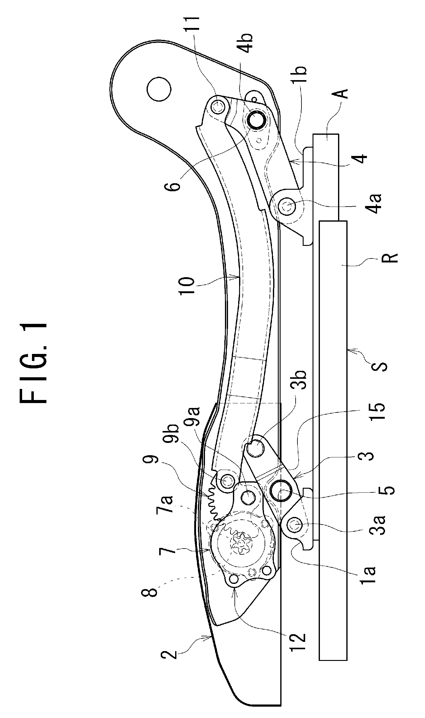
Moreover, the height adjusting device comprises several parts including the forward and rearward linkage members 3, 4 which are supported to the side frames 2 of the seat cushion, and the operating knob 7, the pinion gear 8, the sector gear 9, and the rod 10 which are supported to the one of the side frames 2, so that the structures of the side frame and / or arrangement of the parts around the side frame is likely to become complicated.
Particularly, a considerable load, such as a weight load of the seat itself and / or a weight load of the occupant on the seat, is applied to the support pins 3b, 4b supporting the forward and rearward linkage members 3, 4, and the support pin 9a of the sector gear 9, so that positional relationships among them with respect to the side frame are hard to be determined, and the structure of the height adjusting device is likely to become complicated.
Moreover, in the height adjusting device for the automobile seat, if the rigidity of the linkage base frame 15 is poor and a considerable load is applied to the linkage base frame 15, the forward and rearward linkage members 3, 4 and parts around them are made to flex, so that the seat is hard to be stably supported, and / or it is hard to carry out the adjusting of the height of the seat.
However, the forward linkage member 3 which is arranged in the vicinity of the parts including the operating knob 7, the pinion gear 8, the sector gear 9 and the rod 10 is required not to interfere with their operations, so that the arrangement and shape of the forward linkage member 3 is considerably limited and it is not easy to ensure the good rigidity of the linkage base frame 15.
When the height of the seat is to be adjusted, lifting of the linkage base frame 15 must be performed against the total weight load by only operating the operating knob, so that a considerable force is required in order to operate the operating knob and, therefore, it is hard to operate the operating knob.
Therefore, there is a problem that the height adjusting device becomes large-sized and a lowermost position of the seat is inevitably set so as to become high.
Therefore, in order that they can be effectively and smoothly operated, the structure of the height adjusting device is likely to become complicated.

Method used


Image

  • Seat height adjusting device for automobile
  • Seat height adjusting device for automobile
  • Seat height adjusting device for automobile

Examples


Embodiment Construction

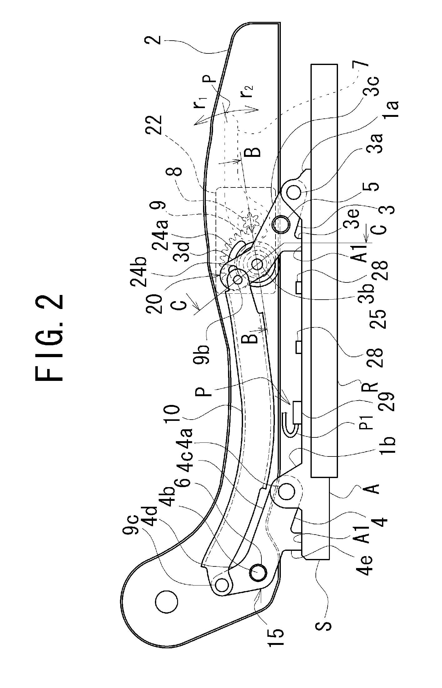
A preferred embodiment of a height adjusting device for adjusting a height of an automobile seat, according to the present invention, will be discussed hereinafter with reference to FIGS. 2 to 8. Referring now to FIG. 2, the height adjusting device is employed as means to adjust a height of an entire seat adapted to be slid forward and rearward via a slide rail mechanism S in an automobile. The slide rail mechanism S comprises a pair of lower rail members R (only one lower rail member R is shown in FIG. 2) mounted on a floor of the automobile, and a pair of upper rail members A (only one upper rail member A is shown in FIG. 2) slidably engaged with the lower rail members R.

In the automobile seat, the height adjusting device includes a linkage base frame 15 as a base thereof. The linkage base frame 15 is provided between forward and rearward brackets 1a, 1b, which are provided on the upper rail members A so as to stand up from the upper rail members A, and spaced apart side frames 2 ...


PUM


Abstract

An automobile seat height adjuster includes a linkage base frame between the seat's side frames and seat brackets so as to be vertically swingable. The base frame has two pairs of linkage members interconnected by respective shafts. Each of the linkage members extends between one of the side frames and one of the brackets so as to be collapsable. A power transmission mechanism transmits to the linkage base frame power generated by operation of an operating knob and causes the linkage base frame to swing vertically, thereby causing the seat to move vertically. Stops on the linkage base frame abut the installation surfaces, limiting downward movement of the seat and keeping the seat in a lowermost position at which side frames of the seat are spaced from the installation surfaces.

Description

TECHNICAL FIELDThe present invention relates to a device for adjusting a height of an automobile seat.BACKGROUND ARTHitherto, there has been proposed an automobile seat which is provided with a height adjusting device for adjusting a height of the automobile seat. Moreover, such a height adjusting device is applied to a slide-type seat for an automobile, which can be slid forward and rearward in the automobile (International Publication No. WO2004 / 094180A1, Japanese Patent Application Laid-Open No. 2000-108734, Japanese Patent Application Laid-Open No. 2000-127813, and Japanese Patent Application Laid-Open No. 2001-138789).Referring now to FIG. 1, an automobile seat provided with the conventional height adjusting device will be discussed hereinafter in order to facilitate understanding of the present invention. The automobile seat includes a slide rail mechanism S which comprises a pair of spaced apart lower rail members R and a pair of spaced apart upper rail members A slidably sup...

Claims


Application Information

Patent Timeline
Patent Type & Authority Patents(United States)
IPC IPC(8): B60N2/16
CPCB60N2/1615B60N2/165B60N2/167B60N2/1675B60N2/168B60N2002/0272B60N2/0272
Inventor HOSHI, MASAYUKISUGIYAMA, SHINJIYOSHIDA, MASAMI
Owner TS TECH CO LTD
Learn More