Apparatus and method for sculpting the surface of a joint

a surface and joint technology, applied in the field of implants and instruments, can solve the problems of complex structure of the joint, difficulty in all joint replacement surgery, and extensive surgical exposur

Inactive Publication Date: 2011-07-26
CAYENNE MEDICAL INC
View PDF17 Cites 12 Cited by
  • Summary
  • Abstract
  • Description
  • Claims
  • Application Information

AI Technical Summary

Benefits of technology

[0014]The present invention provides a system and method for partial or total joint replacement, that is to resurface one or more of the bony surfaces of the joint or motion segment, which involves less or minimally invasive surgical procedures which can be used to place implants that restore joint kinematics. The instruments and implants disclosed accomplish accurate bone and soft tissue preparation, restoration of anatomical alignment, soft tissue balance, kinematics, component to component orientation and alignment, subcomponent to subcomponent orientation and alignment, and implant fixation through limited surgical exposure.
[0025]In another embodiment of the sculpting instrument the cutting elements are designed for two modes of operation; on for cutting and off for no cutting. In the case of a sculpting instrument that uses shaving elements for bone cutting the blades are deployed for cutting and retracted for no cutting. Blade deployment and retraction is manual. Alternatively, blade deployment and retraction is actuated mechanically or hydraulically. For the procedures and embodiments described above, this on / off sculpting instrument eliminates the need for spacers. When the desired resection depth or knee alignment is attained the respective sculpting instrument is turned off. In the case of the robotic TGS instrument system, the system controller is programmed to turn respective sculpting instruments on and off to control resection depth in each compartment to attain a preset knee alignment while the surgeon is flexing and extending the knee. The system displays independent intracompartmental resection depths, knee alignment, soft tissue balance and other variables of interest and prompts the surgeon when desired knee alignment is attained. In another control mode, the robotic TGS instrument system is programmed to monitor resection depth, intracompartmental distraction force and distraction displacement, and knee kinematics continuously throughout the knee's full range of motion and actively control bone resection in each compartment to vary resection throughout the range of motion to provide uniform soft tissue balance, alignment and kinematics throughout the range of motion.

Problems solved by technology

Current methods of preparing a joint to receive implants that replace the articular surfaces or motion segments involve an extensive surgical exposure.
Current implants and instruments for joint replacement surgery have numerous limitations.
Such difficulties are present in all joint replacement surgery.
A difficulty with implanting modular knee implants in which the femur or tibia is resurfaced with multiple components has been achieving a correct relationship between the components.
This may account for the high failure rates in the surgical application of free standing compartmental replacements used individually or in combination.
Surgical instruments available to date have not provided trouble free use in implanting multi-part implants wherein the distal femur, proximal tibia and posterior patella are prepared for precise subcomponent-to-subcomponent and component-to-component orientation and alignment.
While current femoral alignment guides aid in orienting femoral resections relative to the femur and current tibial alignment guides aid in orienting tibial resections relative to the tibia, they provide limited positioning or guidance relevant to correct subcomponent-to-subcomponent alignment or orientation.
Nor do such alignment guides provide guidance relevant to soft tissue balance (i.e. ligament tension to restore soft tissue balance).
Moreover, they provide limited positioning or guidance relevant to correct flexion / extension orientation of the femoral component, to correct axial rotation of the femoral component, nor to correct posterior slope of the tibial component.

Method used


Image

  • Apparatus and method for sculpting the surface of a joint
  • Apparatus and method for sculpting the surface of a joint
  • Apparatus and method for sculpting the surface of a joint

Examples


Embodiment Construction

[0096]Some embodiments of the invention include replacing the articulating surfaces of the knee with implants. Supporting information is included in current patents and patent applications, to include U.S. Pat. Nos. 6,482,209 and 6,723,102, herein incorporated by reference.

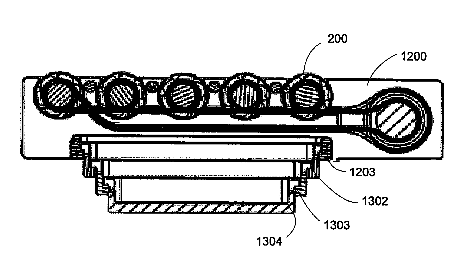
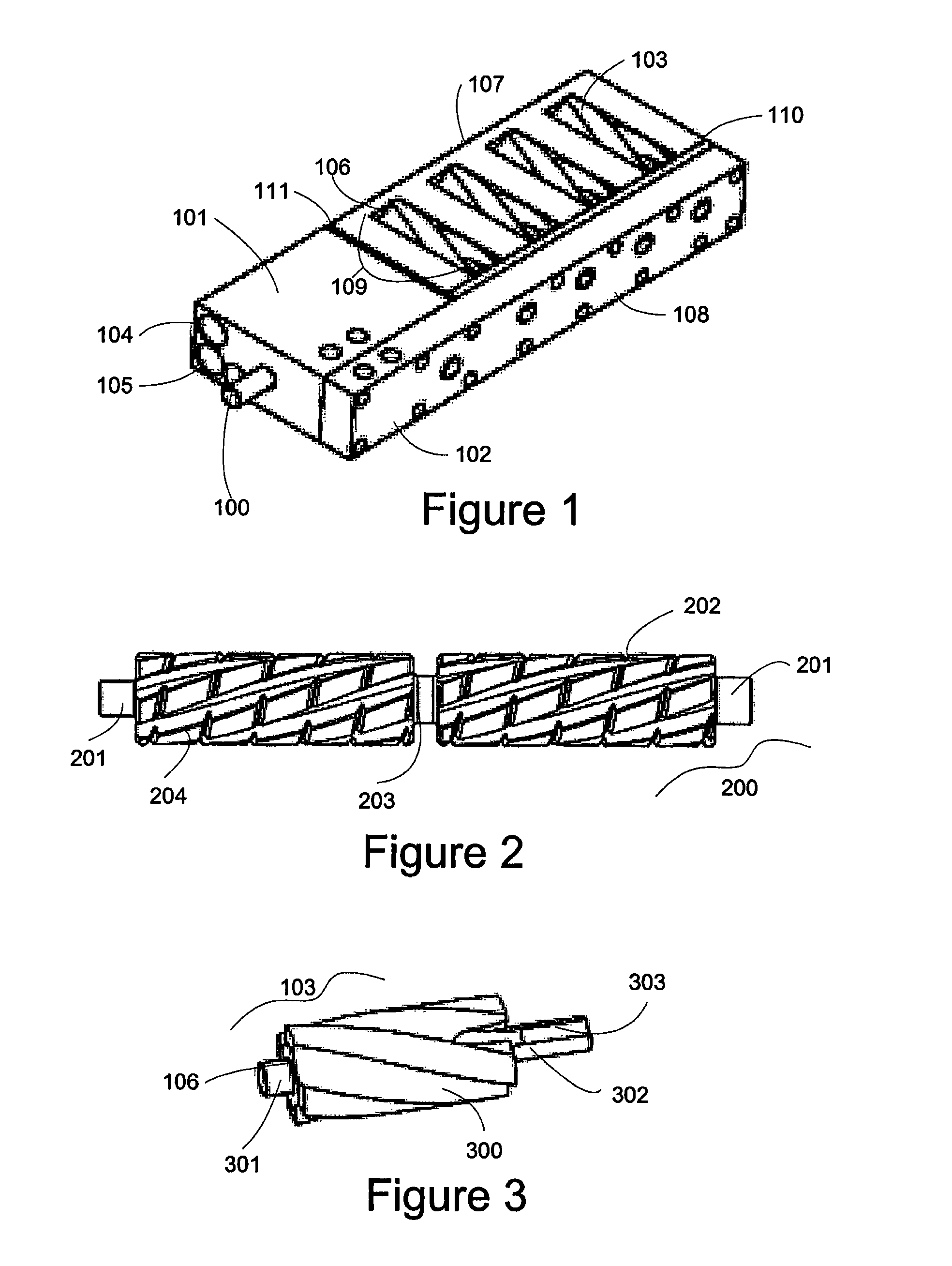
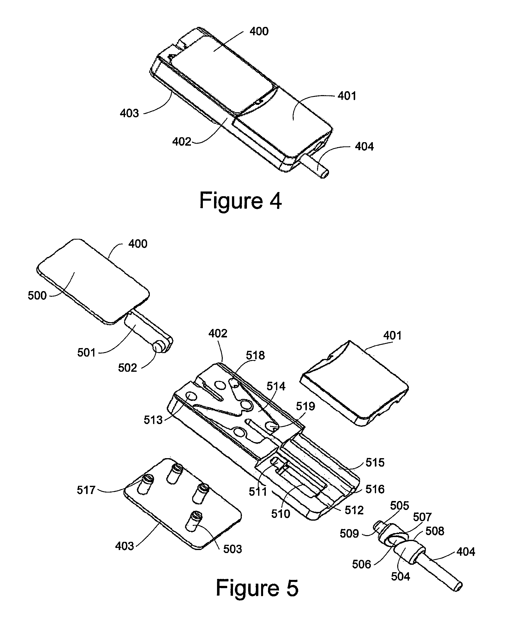
[0097]The present application includes disclosure of bone-sculpting tools for preparing the femoral condyles and trochlea. Sculpting instruments, sculpting instrumentation, sculpting devices, sculpting apparatus and bone-sculpting tools are interchangeable terms. It should be noted that tissue guided surgery and the sculpting device embodiments are applicable to other joints in the body, to include but not limited to the hip, shoulder, ankle; and motion segments of the spine, to include the disc and facet joints. The femoral cutter (sculpting devices) described herein include a shaver (as initially described in U.S. Pat. No. 6,428,209), a barrel cutter, a reciprocating cutter and a belt cutter. Various embodiments...


PUM


Abstract

Methods and devices for sculpting bones, particularly in preparation for implanting prosthetic devices to replace articulating bone joint surfaces. Improved bone removal devices including burr mills driven by gears and loop drives are provided. Reciprocating cutters and belt cutters are also provided. Some devices have either integral or removable expandable portions to vary the force and bone resection depth. Devices can have irrigation ports and plenums to remove bone fragments. Some cutters are dual cutters, adapted to remove bone in two or more regions, such as the knee joint, simultaneously.

Description

CROSS REFERENCE TO RELATED APPLICATIONS[0001]This application claims the benefit of U.S. Provisional Patent Application No. 60 / 746,228, filed May 2, 2006, and is a continuation-in-part of U.S. patent application Ser. No. 11 / 535,916, filed Sep. 27, 2006, which claims the benefit of U.S. Provisional Patent Application No. 60 / 721,450, filed Sep. 28, 2005, and is a continuation-in-part of U.S. patent application Ser. No. 10 / 429,435, filed May 5, 2003, the entireties of which are hereby incorporated by reference.TECHNICAL FIELD[0002]This invention relates to implants and instruments for use in cutting and preparing bone, for example, in total and partial knee arthroplasty. Such instruments are applicable in other total and partial joint replacement surgeries which include, but are not limited to the hip, the shoulder, the ankle, the elbow, the joints of the hand, the joints of the wrist, the joints of the foot and the temporal mandibular joint, articulating joints such as the knee and hi...

Claims


Application Information

Patent Timeline
Patent Type & Authority Patents(United States)
IPC IPC(8): A61B17/00
CPCA61B17/1675A61B17/1624A61B2017/0268A61B2017/0275A61B2017/1602A61B17/1662A61B2017/00539A61B17/32002
Inventor JOHNSON, WESLEY D.ENGH, GERARD A.KOHLER, ROBERT E.BISEK, AARON J.TRAVANTY, MICHAEL N.PILARSKI, DARYL R.
Owner CAYENNE MEDICAL INC
Why Eureka
Try Eureka