
Electronic devices based on current induced magnetization dynamics in single magnetic layers

a current induced magnetization and electric device technology, applied in the field of electric devices, can solve the problems of junction resistance hysteretic changes, significant resistance changes, reversible excitations,

Inactive Publication Date: 2011-07-26
NEW YORK UNIV
View PDF7 Cites 107 Cited by
  • Summary
  • Abstract
  • Description
  • Claims
  • Application Information

AI Technical Summary

Problems solved by technology

For MRAM applications one of the key challenges is to reduce the current and power needed change the magnetization state and induce magnetization precession.
A further challenge is to have a significant change in resistance so as to have a large device output signal.
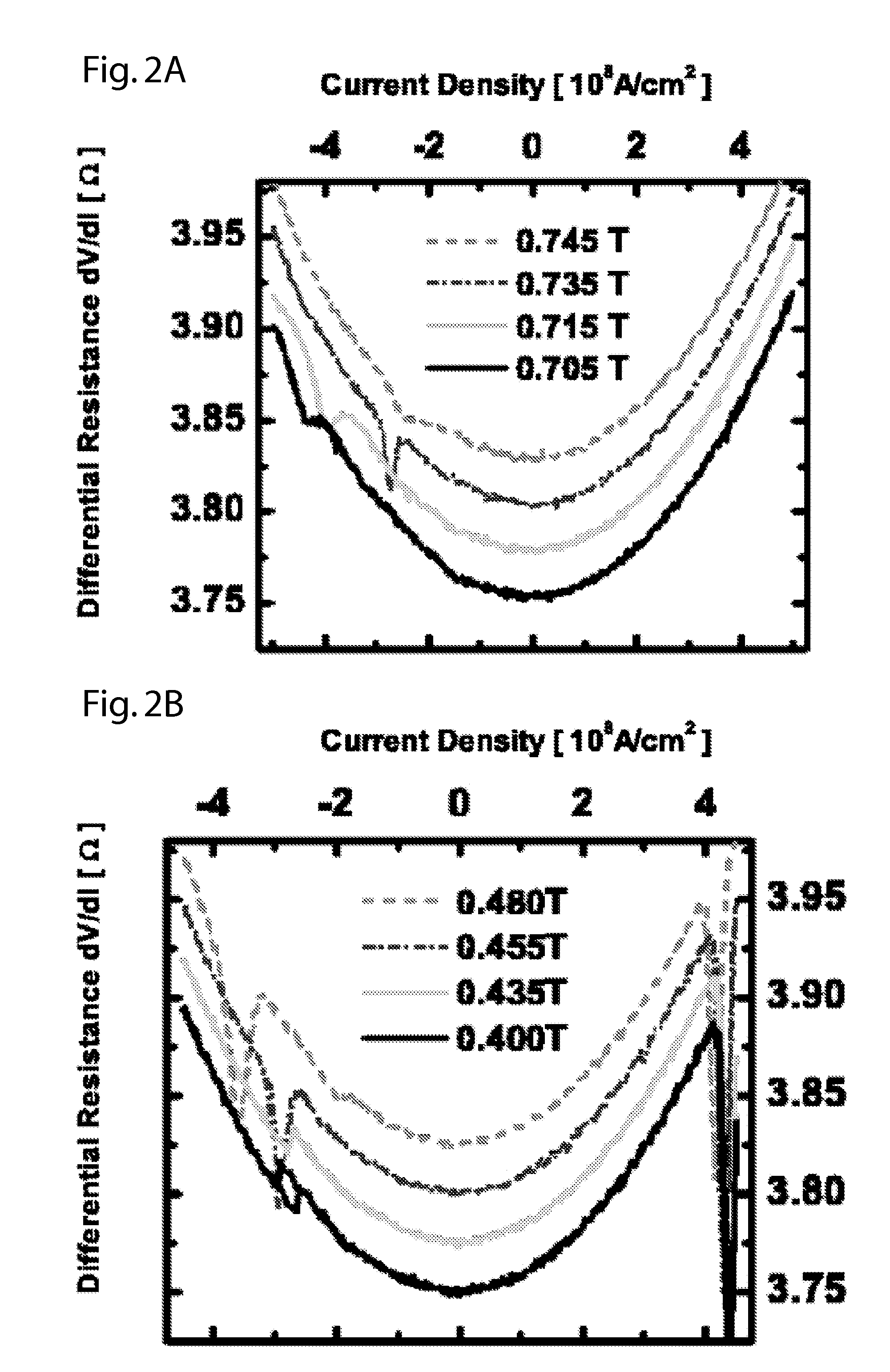
In magnetic fields below the demagnetization field, spin transfer may lead to both reversible excitations and hysteretic changes in the junction resistance.

Method used


Image

  • Electronic devices based on current induced magnetization dynamics in single magnetic layers
  • Electronic devices based on current induced magnetization dynamics in single magnetic layers
  • Electronic devices based on current induced magnetization dynamics in single magnetic layers

Examples


Embodiment Construction

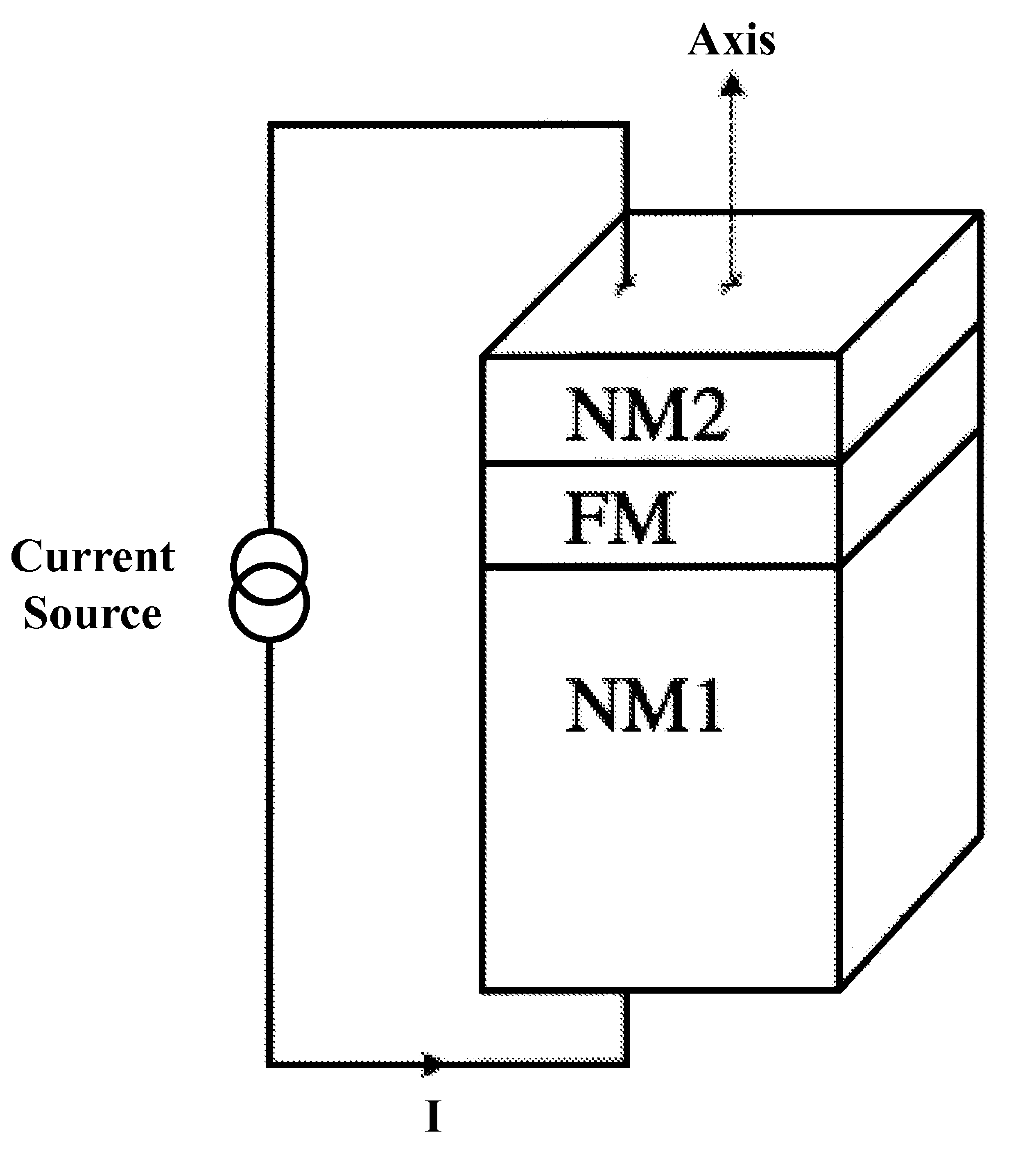
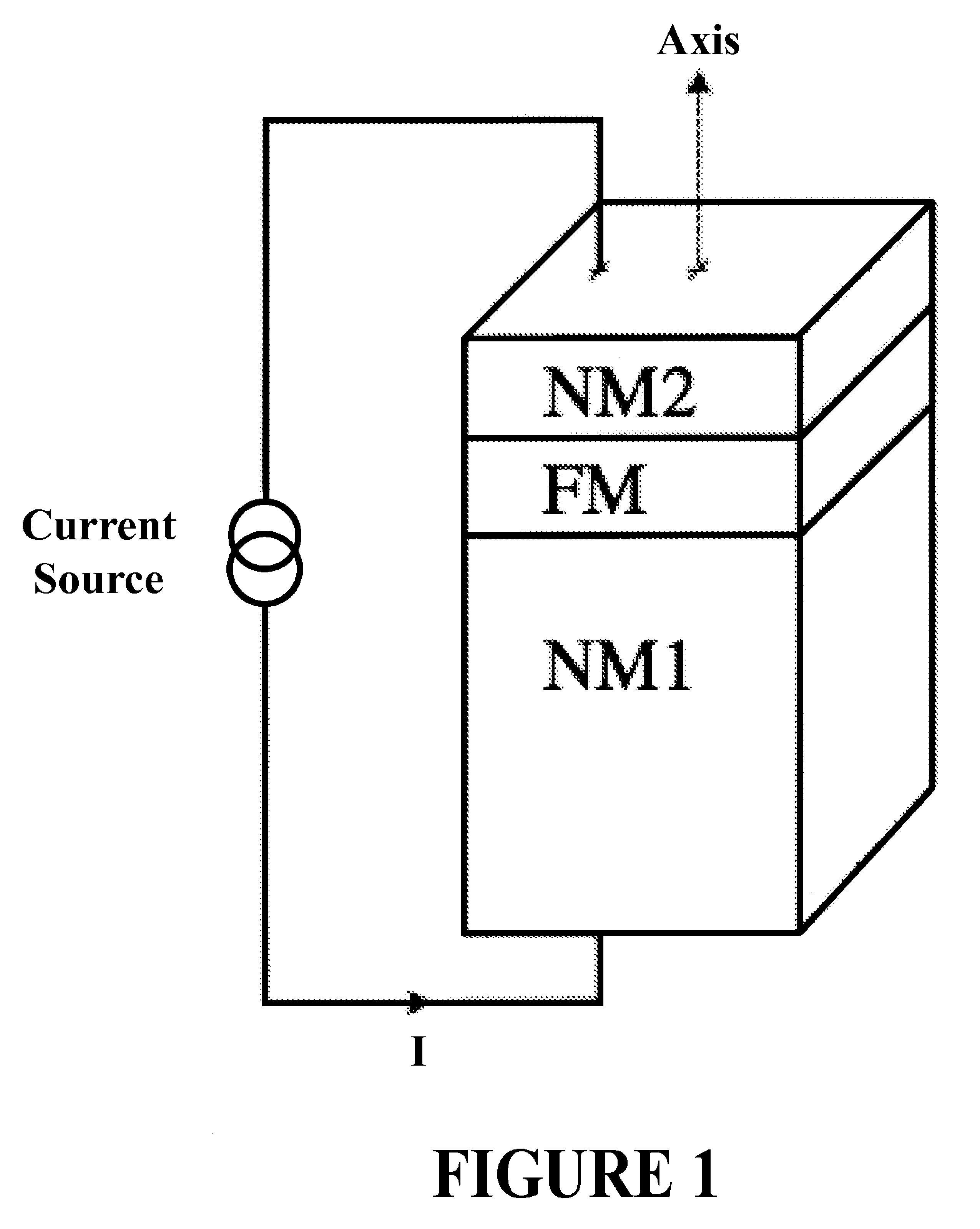
[0022]Non-uniform magnetization can be achieved in accordance with the present invention in a number of different ways. The magnetization state of a thin magnetic layer is typically non-uniform to reduce the magnetostatic energy of the layer. The degree of non-uniformity depends on many factors. One way to create a non-uniform configuration is through the shape of the magnetic element. For example, a thin disc may lead to a vortex state in which the magnetization circulates around the center of the disk; a rectangular or elliptical shape will have a magnetization that is aligned with the long axis of the rectangle or ellipse, but at the ends will deviate—there are at least two possible deviations, i.e., where the magnetization at the ends point in the same direction or in opposite directions. A second approach may be the growth of ferromagnetic layers on surfaces, which have an intrinsic roughness either due to the presence of roughness in an underlying layer or due to presence of g...


PUM


Abstract

The present invention generally relates to magnetic devices used in memory and information processing applications, such as giant magneto-resistance (GMR) devices and tunneling magneto-resistance devices. More specifically, the present invention is directed to a single ferromagnetic layer device in which an electrical current is used to control and change magnetic configurations as well as induce high frequency magnetization dynamics. The magnetic layer includes full spin-polarized magnetic material, which may also have non-uniform magnetization. The non-uniform magnetization is achieved by varying the shape or roughness of the magnetic material. The present invention may be used in memory cells, as well as high frequency electronics, such as compact microwave sources, detectors, mixers and phase shifters.

Description

[0001]This application claims the priority under 35 U.S.C. §120 of U.S. Provisional Application No. 60 / 856,556 filed on Nov. 3, 2006, which is incorporated herein by reference in its entirety.[0002]This invention was made with government support under Contract Nos. NSF-DMR-0405620 and NSF-DMR-0706322. The U.S. Government has a paid-up license in this invention and the right in limited circumstances to require the patent owner to license others on reasonable terms as provided for by the terms of Grant Nos. NSF-DMR-0405620 and NSF-DMR-0706322 awarded by the National Science Foundation.FIELD OF THE INVENTION[0003]The present invention generally relates to magnetic devices used in memory and information processing applications, such as giant magneto-resistance (GMR) devices and tunneling magneto-resistance devices. More specifically, the present invention describes a device that requires only one ferromagnetic layer.BACKGROUND OF THE INVENTION[0004]Devices using spin-momentum transfer, ...

Claims


Application Information

Patent Timeline
Patent Type & Authority Patents(United States)
IPC IPC(8): G11C11/00
CPCG11C11/16H01L43/08H01F10/193H01F1/404G11C11/161G11C11/1673G11C11/1675H10N50/10
Inventor KENT, ANDREWOZYILMAZ, BARBAROS
Owner NEW YORK UNIV
Learn More