Fork configuration dampers and method of using same

a configuration damper and fork technology, applied in the direction of vibration dampers, spring/damper design characteristics, building components, etc., can solve the problems of increased increased vibration, occupant discomfort, etc., and achieve the effect of increasing the damping in the structure and increasing the damping

Active Publication Date: 2011-08-02
THE GOVERNING COUNCIL OF THE UNIV OF TORONTO +1
View PDF21 Cites 21 Cited by
  • Summary
  • Abstract
  • Description
  • Claims
  • Application Information

AI Technical Summary

Benefits of technology

[0011]According to another aspect of the invention there is provided a method of increasing the damping in a structure comprising the steps of installing between two adjacent lateral load resisting structural elements of a structure at least one damping system as described above.

Problems solved by technology

Due to this low inherent damping, high-rise buildings, in particular, tend to be susceptible to excessive vibrations caused by dynamic loads.
Excessive accelerations and torsional velocities can cause occupant discomfort, while excessive displacements can cause damage to non-structural and structural elements.
While this may be effective in adding damping to some structural configurations, where under this typical braced configuration the brace elements undergo significant axial deformations, they are less effective for other structural systems, such as high rise buildings where the primary mode of lateral deformation does not cause sufficient axial deformation in typical bracing elements to actuate such dampers.
This has the disadvantage of using up some of the most valuable real estate within the building in addition to being expensive to design and to build.
As a result, they are expensive to design and implement, and are susceptible to power outages or failure of the control system.

Method used


Image

  • Fork configuration dampers and method of using same
  • Fork configuration dampers and method of using same
  • Fork configuration dampers and method of using same

Examples


Embodiment Construction

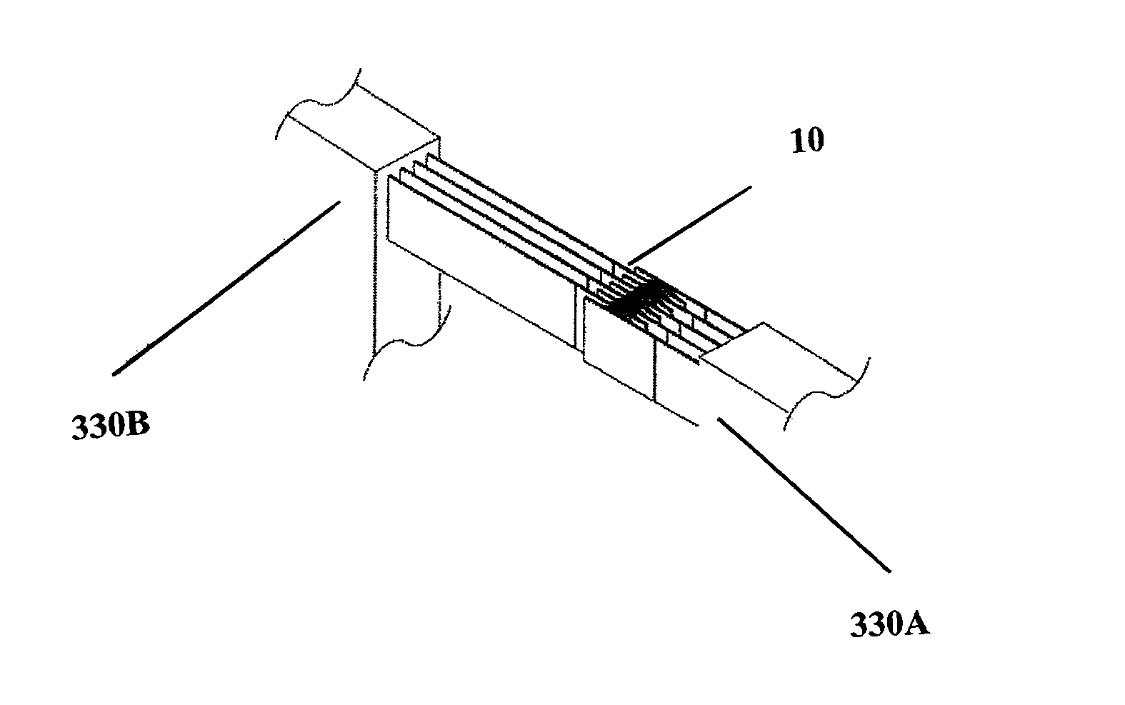
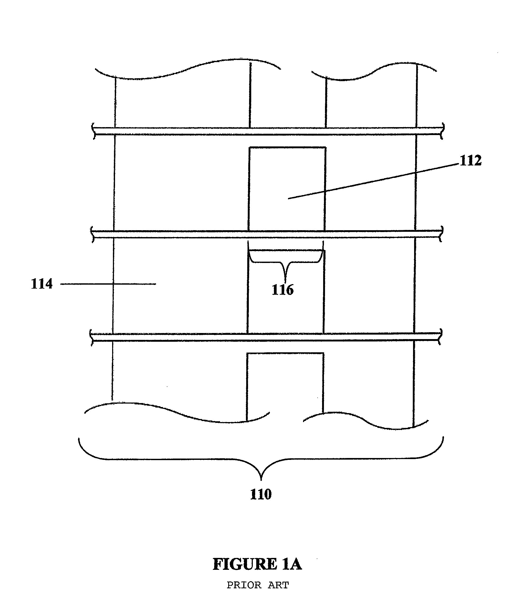
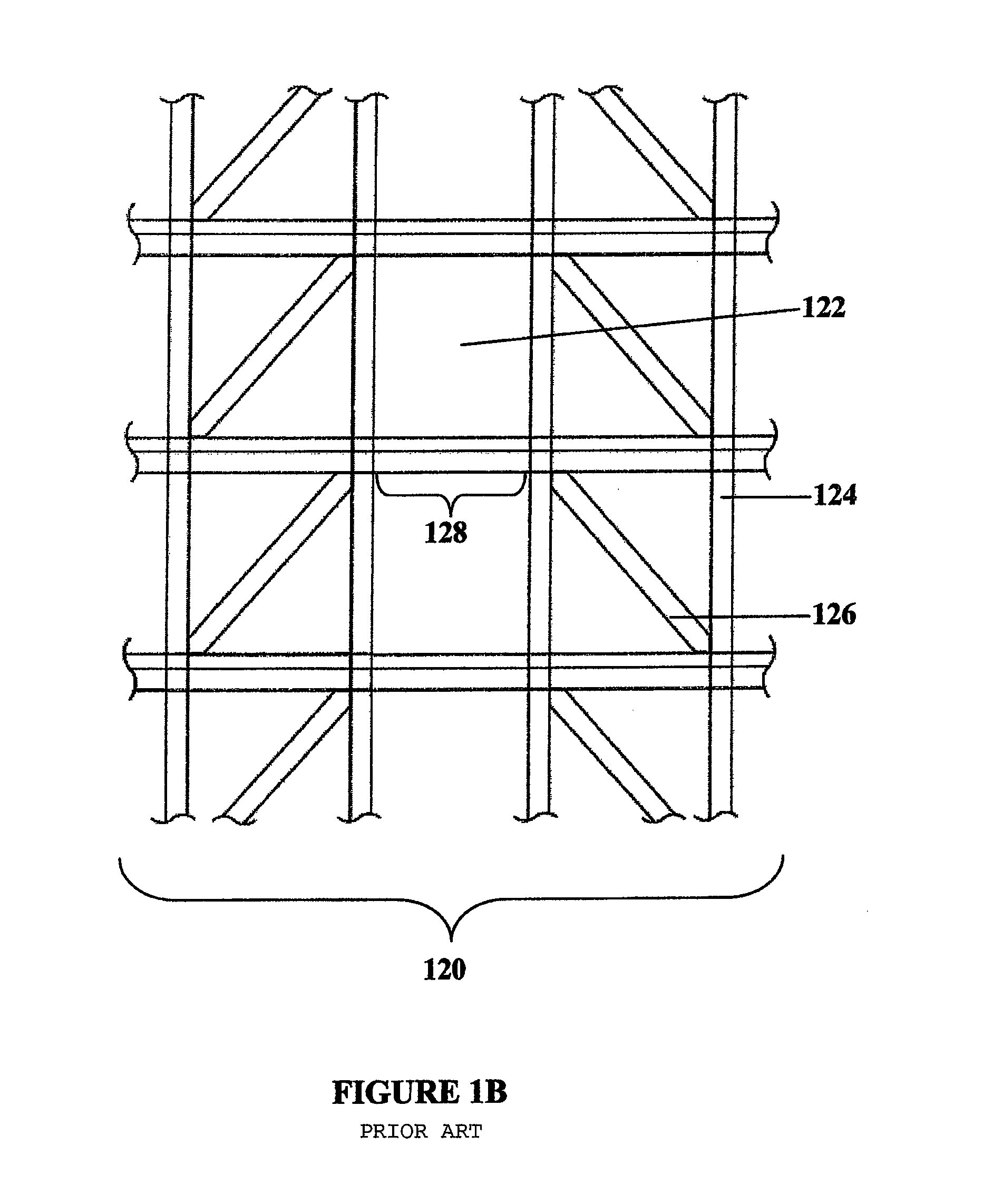
[0031]Referring now to FIGS. 1A-1E, examples of the present state of the art for the construction of mid and high-rise buildings is shown, namely using coupled reinforced concrete shear walls 114 (FIG. 1A), structural steel braced frames 120 (FIG. 1B), structural steel or reinforced concrete moment frames 130 (FIG. 1C), combinations thereof 140 (FIG. 1D), and construction with outer columns 152 (concrete or steel or any other material as used in the field of construction) and internal shear walls 156 (FIG. 1E). As a building is subject to wind or seismic loads, the coupling beams (116, 128, 134, 144, 154) or lateral braces (126, 148) are deformed, without providing any significant damping.

[0032]Referring to FIG. 1A, a structure 110 using reinforced concrete shear walls 114 has concrete coupling beams 116 located in the openings 112 between the shear walls 114. Similarly, a structure 120 using steel columns 124 and braces 126, as shown in FIG. 1B has steel coupling beams 128 located ...


PUM


Abstract

A new configuration damper, for interconnecting two elements of a structure that undergo relative movements and deformations, that increase the level of damping when the overall structure is subjected to a loading condition is disclosed. The new configuration damper aides in controlling displacements, velocities and accelerations under dynamic loading in structural systems.

Description

FIELD OF THE INVENTION[0001]The present invention relates to the field of damping systems for buildings, bridges and other structures. In particular, it relates to a new configuration damper, for interconnecting two elements of a structure that undergo relative movements and deformations, that increases the level of damping when the overall structure is subjected to a loading condition. The new configuration damper aids in controlling displacements, forces, velocities and accelerations under dynamic loading in structural systems.BACKGROUND OF THE INVENTION[0002]Modern buildings, using typical construction components such as reinforced concrete shear walls, structural steel braced frames, structural steel or reinforced concrete moment frames or combinations thereof, have low inherent damping properties. Due to this low inherent damping, high-rise buildings, in particular, tend to be susceptible to excessive vibrations caused by dynamic loads. Excessive accelerations and torsional vel...

Claims


Application Information

Patent Timeline
Patent Type & Authority Patents(United States)
IPC IPC(8): E04H9/02
CPCE04H9/022F16F15/02F16F1/50F16F1/40E04H9/0237E04B1/98E04H9/021F16F2230/0023F16F2238/04
Inventor CHRISTOPOULOS, CONSTANTINMONTGOMERY, MICHAELKOKAI, TIBORSMITH, SEANHASAN, AGHABENTZ, EVANCOLLINS, MICHAEL
Owner THE GOVERNING COUNCIL OF THE UNIV OF TORONTO
Why Eureka
Try Eureka