Variable valve lift apparatus

a technology of valve lift and valve body, which is applied in the direction of valve details, valve arrangements, valve drives, etc., can solve the problems of insufficient valve open time and amount, inability to adjust the amount of gas being introduced or exhausted, and inability to achieve high speed. , to achieve the effect of reducing manufacturing costs and simple structur

Inactive Publication Date: 2011-08-02
HYUNDAI MOTOR CO LTD
View PDF7 Cites 44 Cited by
  • Summary
  • Abstract
  • Description
  • Claims
  • Application Information

AI Technical Summary

Benefits of technology

Embodiments of the present invention provide a variable valve lift apparatus that may realize a high lift mode and a low lift mode according to an operation condition of a vehicle, which may reduce manufacturing cost with a simple structure.
A variable valve lift apparatus according to an exemplary embodiment of the present invention may reduce manufacturing cost with a simple structure.

Problems solved by technology

Therefore, it is impossible to adjust the amount of a gas that is being introduced or exhausted.
If the valve lift apparatus is designed for low driving speeds, the valve open time and amount are not sufficient for high speeds.

Method used


Image

  • Variable valve lift apparatus
  • Variable valve lift apparatus
  • Variable valve lift apparatus

Examples


Embodiment Construction

An exemplary embodiment of the present invention will hereinafter be described in detail with reference to the accompanying drawings.

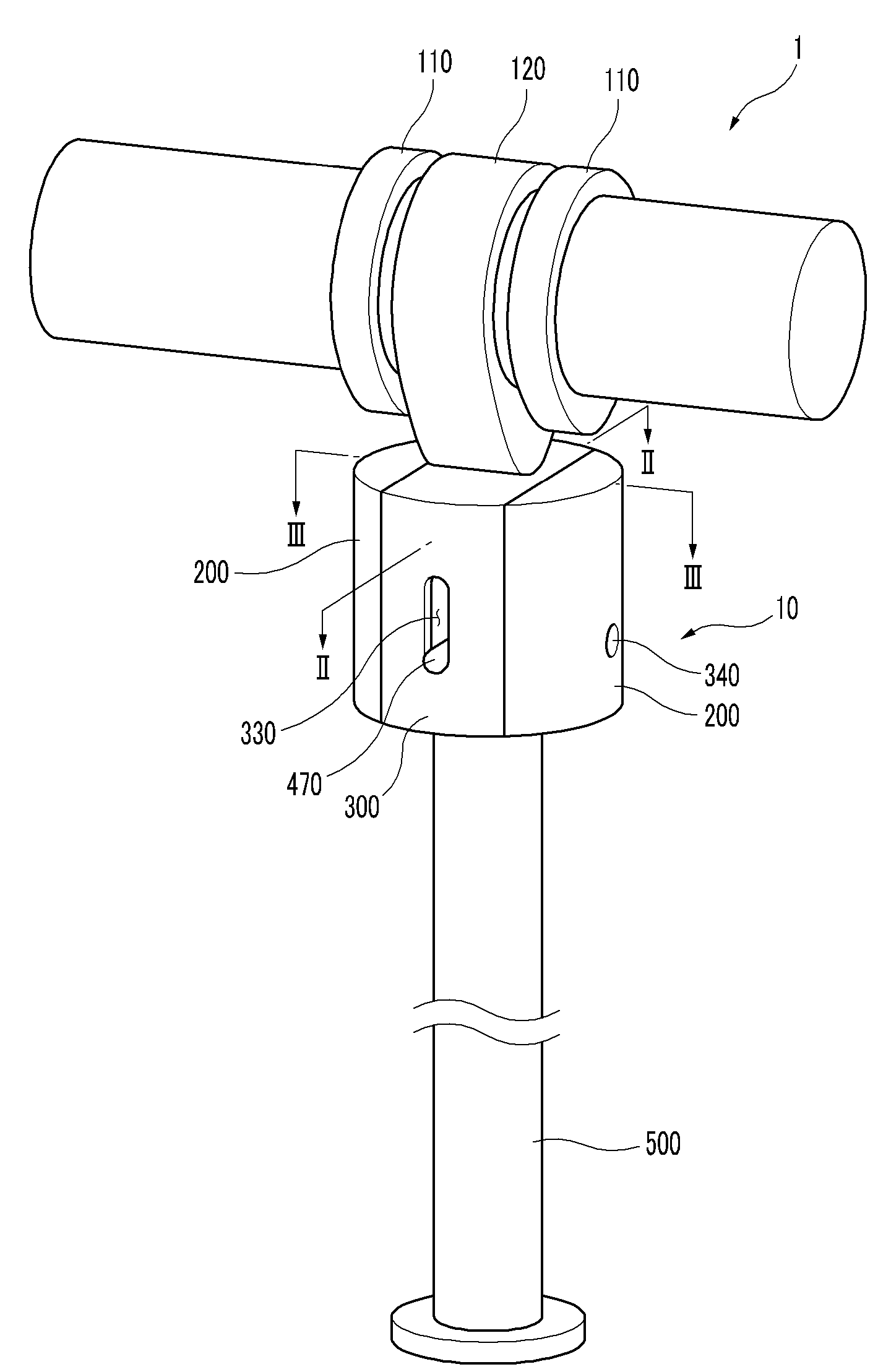
Referring to FIG. 1 to FIG. 3, a variable valve lift apparatus 1 according to an exemplary embodiment of the present invention includes at least a low lift cam 110, a high lift cam 120 disposed in parallel with the low lift cam 110, and a tappet body 10. Preferably, the high lift cam 120 is disposed between two low lift cams 110.

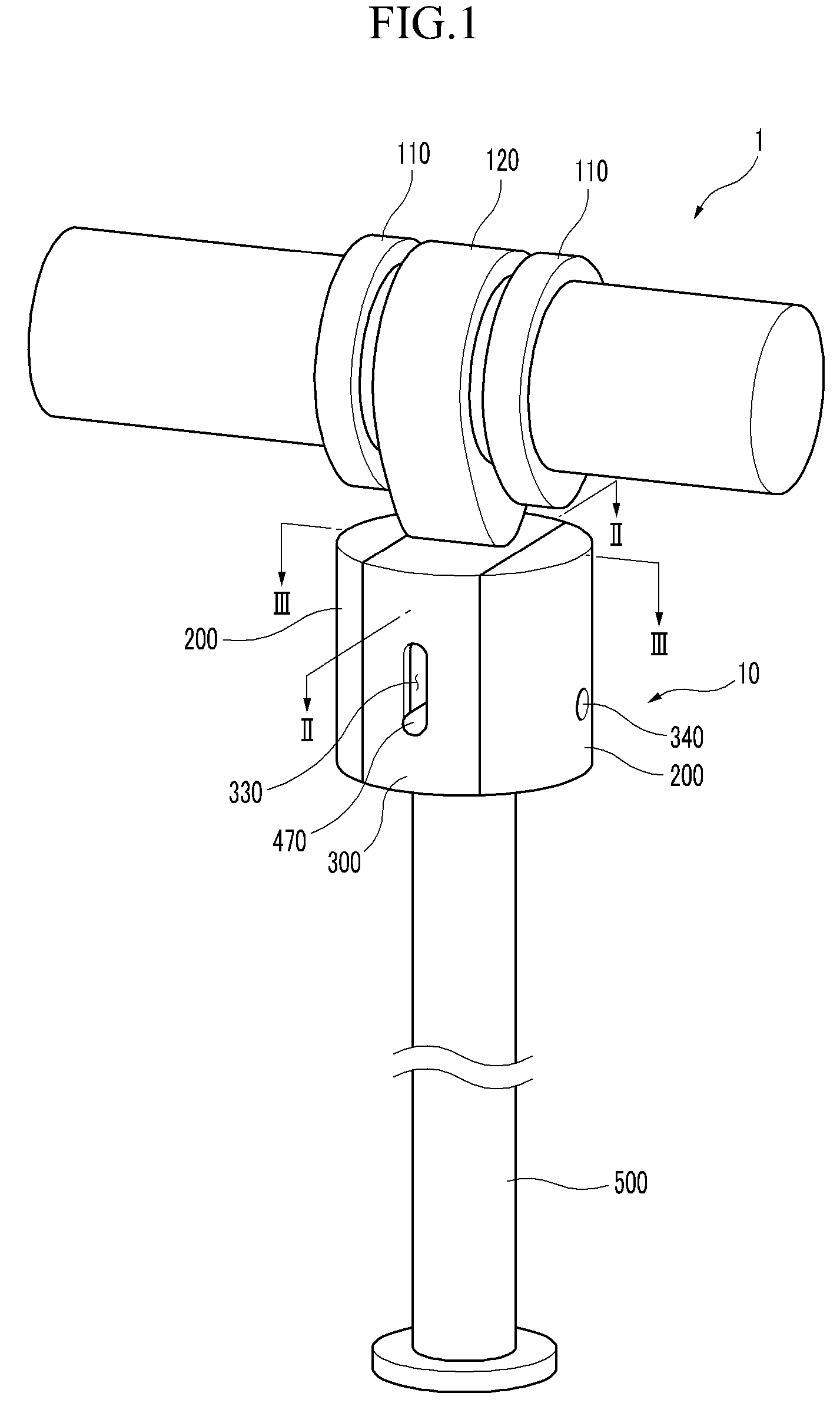
The tappet body 10 includes a low lift tappet body 200 that selectively contacts the low lift cam 110, and a high lift tappet body 300 that is disposed between the low lift tappet bodies 200 and constantly contacts the high lift cam 120.

The variable valve lift apparatus 1 includes a guide portion 400 that is connected with a valve 500 via a mounting bracket 490 and selectively connects the low lift tappet body 200 with the high lift tappet body 300, and a lost motion spring 480 that is disposed between the guide portion 400 and...


PUM


Abstract

A variable valve lift apparatus according to an exemplary embodiment of the present invention includes a low lift cam, a high lift cam in parallel with the low lift cam, a low lift tappet body that selectively contacts the low lift cam, a high lift tappet body disposed within the low lift tappet body and constantly contacting the high lift cam, a guide portion that is connected with a valve and selectively connects the low lift tappet body and the high lift tappet body, and a lost motion spring that is disposed between the guide portion and the low lift tappet body and supplies restoring force to the low lift tappet body.

Description

CROSS-REFERENCE TO RELATED APPLICATIONThis application claims priority to and the benefit of Korean Patent Application No. 10-2007-0131565 filed in the Korean Intellectual Property Office on Dec. 14, 2007, the entire contents of which are incorporated herein by reference.BACKGROUND OF THE INVENTION(a) Field of the InventionThe present invention relates to a variable valve lift apparatus. More particularly, the present invention relates to a variable valve lift apparatus that may realize a cylinder deactivation function with a simple structure.(b) Description of the Related ArtA typical combustion chamber of an automotive engine is provided with an intake valve for supplying an air / fuel mixture and an exhaust valve for expelling burned gas. The intake and exhaust valves are opened and closed by a valve lift apparatus connected to a crankshaft.A conventional valve lift apparatus has a fixed valve lift amount due to a fixed cam shape. Therefore, it is impossible to adjust the amount of...

Claims


Application Information

Patent Timeline
Patent Type & Authority Patents(United States)
IPC IPC(8): F01L1/34
CPCF01L1/053F01L1/143F01L13/0031F01L13/00F01L1/14F01L1/24F01L1/04
Inventor KWAK, YOUNG HONGKWON, KIYOUNGSHIN, KI UKKONG, JIN KOOK
Owner HYUNDAI MOTOR CO LTD
Why Eureka
Try Eureka