
Streamlined diagnostic MR imaging requiring only three control parameters of operator selected boundary conditions

a technology of mr imaging and control parameters, applied in the field of magnetic resonance system operation, can solve the problems of not being able to optimize the stored sequence for all possible applications, not being able to easily see the effects of the operator's change, and complicating matters, so as to achieve the effect of significantly simplifying the creation of measurement protocols

Inactive Publication Date: 2011-08-02
SIEMENS HEALTHCARE GMBH
View PDF11 Cites 10 Cited by
  • Summary
  • Abstract
  • Description
  • Claims
  • Application Information

AI Technical Summary

Benefits of technology

The present invention provides a method for operating a magnetic resonance system that simplifies the creation of measurement protocols. The user only needs to set the desired contrast response, while the control device automatically determines the other necessary parameters. The method can be used with different sequences and field strengths, and can adapt to the patient's position in the system. The method allows for the acquisition of arbitrary data sets with minimal knowledge and can be tailored to the user's specifications. The technical effect of the invention is to simplify the operation of magnetic resonance systems and make it more user-friendly.

Problems solved by technology

For other control parameters, however, the effects when changed by the operator are not readily apparent.
In spite of the presence of a specific sequence in the memory device of the control device, the stored sequence is thus not optimized for all possible applications.
It further complicates matters that a number of sequences are known in magnetic resonance tomography.
The generation of new protocols with existing sequences is accordingly even more complicated for physicians or medical technology employees.
Problems also arise when apparatuses of different manufacturers are used.
Normally no uniform names from manufacturer-to-manufacturer are provided for identical sequences, such that a user can have problems upon operation if he or she must operate with a new apparatus that is possibly unknown to the operator or is only rarely used.
Known methods for automation of the magnetic resonance measurements do not provide assistance in this regard.

Method used


Image

  • Streamlined diagnostic MR imaging requiring only three control parameters of operator selected boundary conditions
  • Streamlined diagnostic MR imaging requiring only three control parameters of operator selected boundary conditions
  • Streamlined diagnostic MR imaging requiring only three control parameters of operator selected boundary conditions

Examples


Embodiment Construction

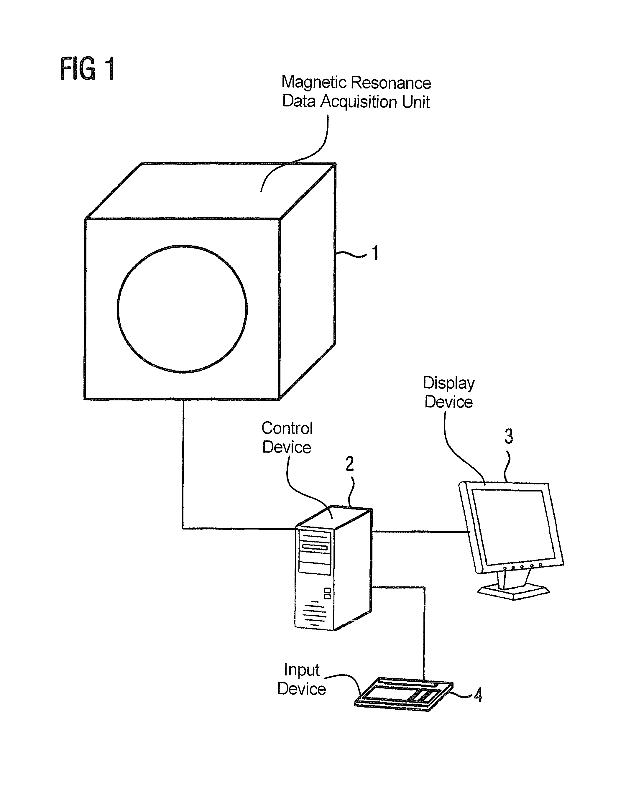
[0025]FIG. 1 shows a magnetic resonance data acquisition unit (scanner) 1 with a control device 2 and a display device 3 and an input device 4 associated with the control device 2. Details of the magnetic resonance system in the form of a radio-frequency coil and the like are well known to those skilled in the art and therefore need not be presented in detail herein.

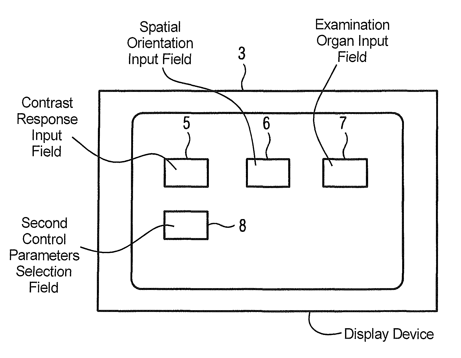
[0026]FIG. 2 shows a basic representation of the display device 3 as it is presented to the user after authentication. The input field 7 is available for selection of the examination organ in addition to the input field 5 for the contrast response and the input field 6 for the spatial orientation. Furthermore, the selection field 8 with which the input fields for the second control parameters can be opened is available for experienced users.

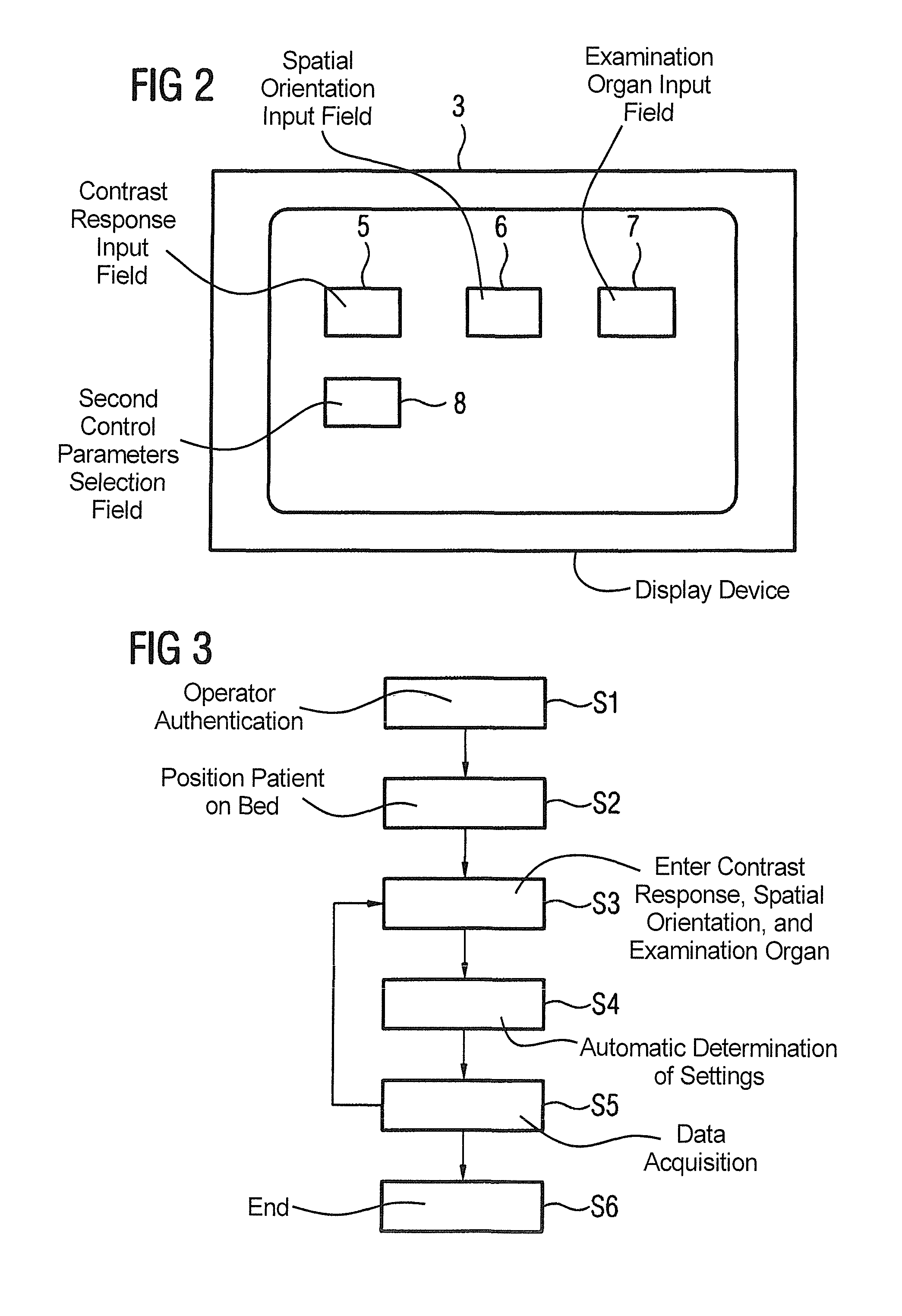
[0027]The workflow for measurement data acquisition on a patient is hereby significantly simplified, as is apparent in FIG. 3. In a first Step S1, the operator authenticates himself o...


PUM


Abstract

In a method for operation of a magnetic resonance system, at least one control device is fashioned for image data acquisition and corresponding components, and only three first control parameters defining primary boundary conditions are selected by an operator of the system, namely the contrast response, the spatial orientation of the at least one image data set to be acquired and the examination organ. Additional, second control parameters, required to control the components for image acquisition and defining secondary boundary conditions, are automatically determined by the control device using the first control parameters.

Description

BACKGROUND OF THE INVENTION[0001]1. Field of the Invention[0002]The present invention concerns a method to operate a magnetic resonance system of the type having at least one control device fashioned for image data acquisition, and corresponding components.[0003]2. Description of the Prior Art[0004]Computerized procedures known as measurement protocols are typically used to operate a magnetic resonance system. In addition to the measurement sequence defining the temporal arrangement of radio-frequency pulses, magnetic field gradients and acquisition points in time, are all relevant control parameters which are defined in these measurement protocols. When the system operator loads such a protocol, he or she can begin the measurement (i.e. the diagnostic imaging) data acquisition with the preset control parameters; otherwise the operator is forced to set the control parameters more or less by hand.[0005]The control parameters include parameters whose meaning can easily be determined, ...

Claims


Application Information

Patent Timeline
Patent Type & Authority Patents(United States)
IPC IPC(8): G01V3/00
CPCA61B5/055A61B5/7207G01R33/543G01R33/546
Inventor WOHLFARTH, KATRIN
Owner SIEMENS HEALTHCARE GMBH
Learn More