One step binary summarizer

a summarizing and binary technology, applied in the field of digital arithmetic circuits, can solve the problems of further slowing down the subtraction operation, and achieve the effects of eliminating the need and/or utilization, reducing the need for subtraction, and simplifying the circuit topographies

Inactive Publication Date: 2011-08-02
SOHAY LESLIE IMRE
View PDF20 Cites 8 Cited by
  • Summary
  • Abstract
  • Description
  • Claims
  • Application Information

AI Technical Summary

Benefits of technology

[0013]This device would perform comparison, addition, and subtraction operations simultaneously, regardless of the operands signs and values, therefore it would have the same speed or performance for all three operations. This device would perform all three operations, without the need for using complement operations on the operands, iterative additions, temporary storage devices, pre evaluating the operands for the possibility of the need of swapping of them or using additional instruction sets for the subtraction operation. Further, this device would perform both addition and subtraction operations using the same concept of “carry” used in the addition operations, instead of the borrow concept to perform a subtraction operations. Further, this device would use the same logic gate functions for addition and subtraction operations, thereby simplifying circuit topographies. It would eliminate the need and / or the utilization of a separate comparator, adder and subtractor circuits. More importantly it would lower the overall time required for the subtraction and comparison operations to the level of the addition operation. Therefore, the time requirements for all three operations would be identical and constant.

Problems solved by technology

Further, subtraction operations performed by most prior art circuits require the use of temporary storage devices such as a flip-flop to keep track of the iterating results.
However, the swapping operation between the operands of two registers is time consuming, which further slows the subtraction operation.

Method used


Image

  • One step binary summarizer
  • One step binary summarizer
  • One step binary summarizer

Examples


Embodiment Construction

[0039]The detailed description set forth below in connection with the appended drawings is intended as a description of presently preferred embodiments of the invention and is not intended to represent as the only forms in which the present invention may be constructed and / or utilized.

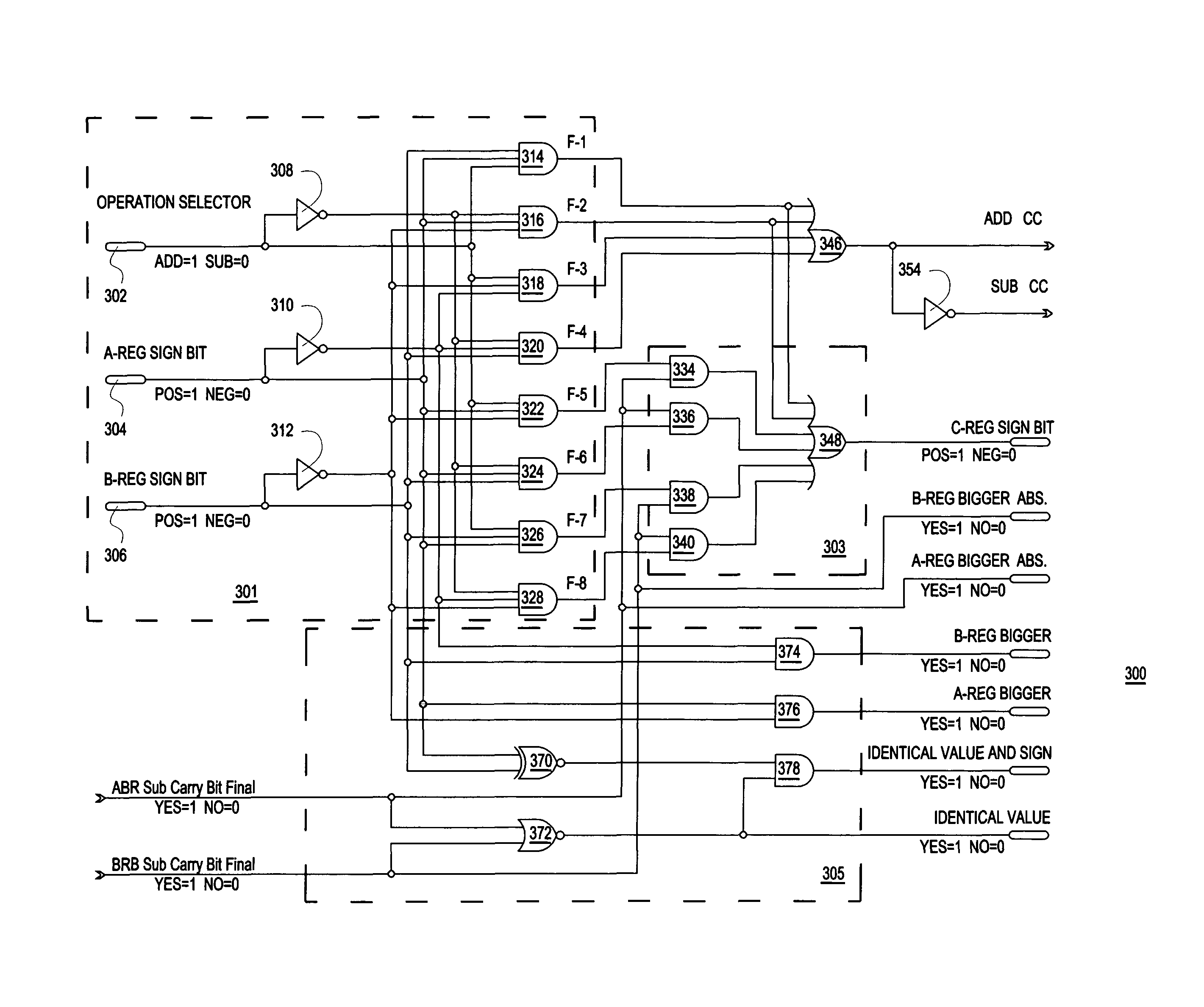
[0040]For purposes of illustration, the various circuit topographies illustrated throughout the disclosure use logic gates, which are symbolic representations of logic functions. The disclosure should not be limited by any specific symbol, logic gate, or any other representation of a logic function, but by the actual logic function itself. Non-limiting examples of logic gates representing logic functions may include AND, NAND, OR, NOR, XOR, XNOR, INV (inverter), or a combination thereof, etc.

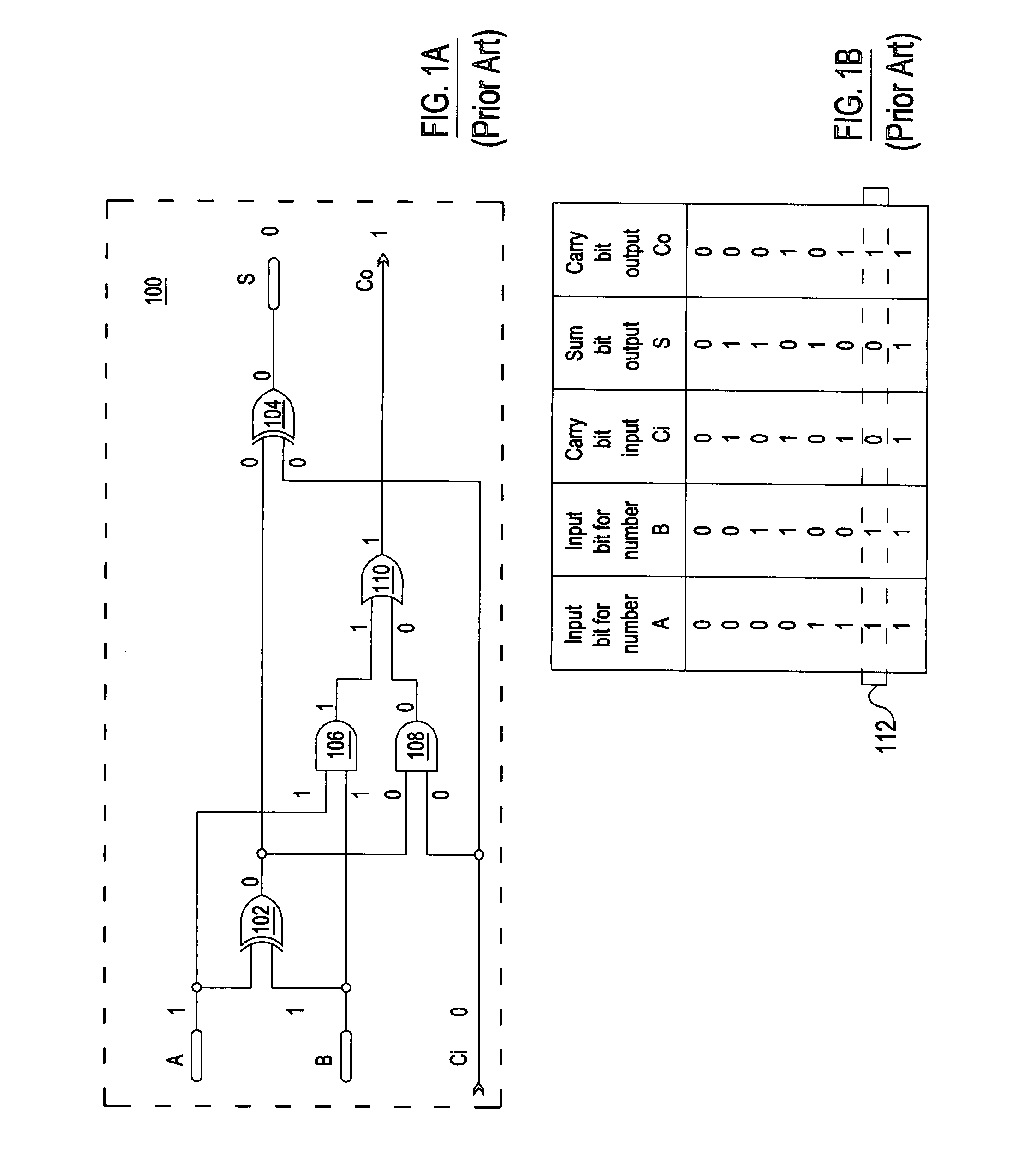
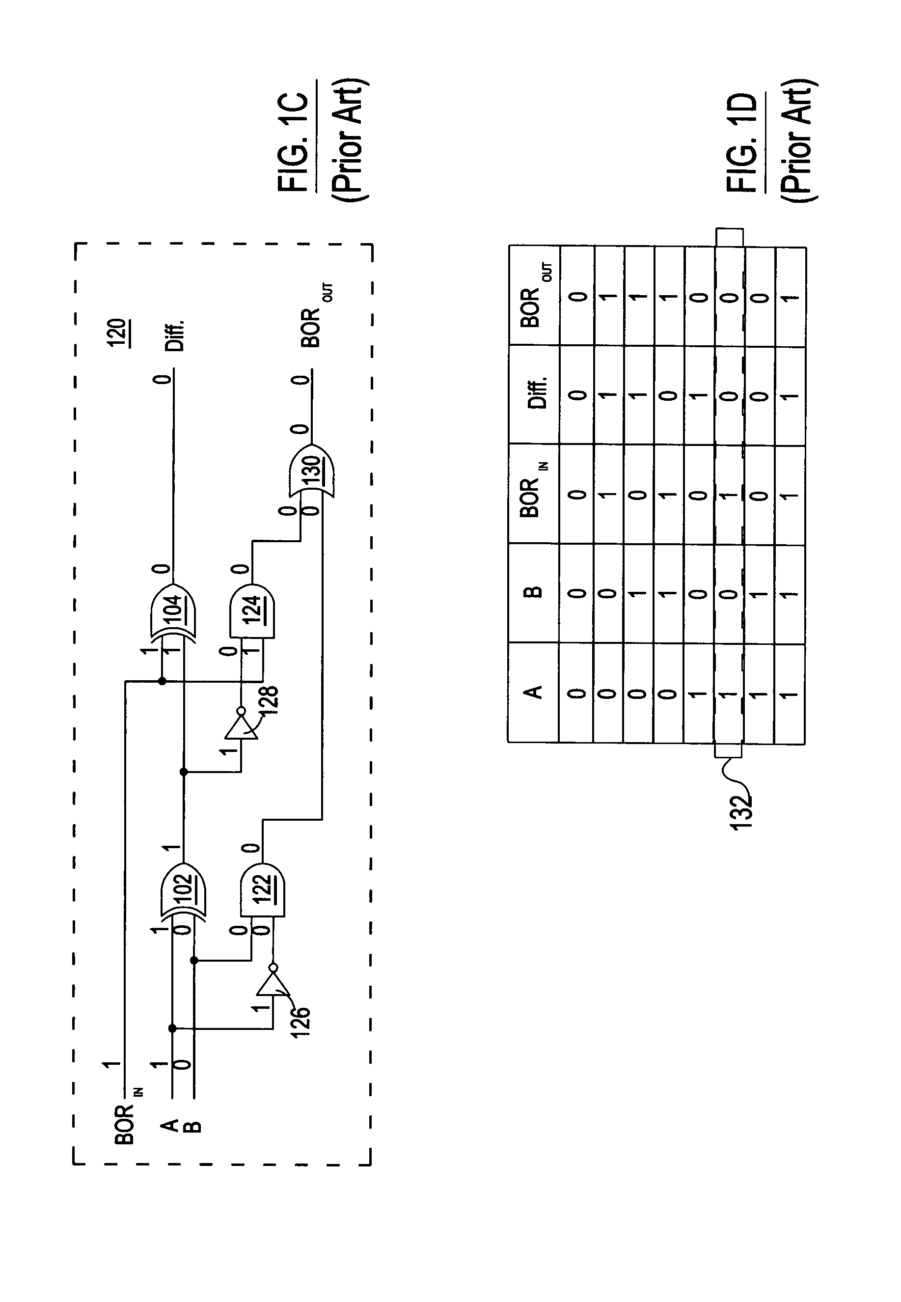
[0041]Conventional arithmetic logic circuits use 1's or 2's compliment operations on operands to perform a subtraction operation, which in fact, implements the borrow concept of subtraction in digital format. The p...


PUM


Abstract

The ONE STEP BINARY SUMMARIZER is a digital logic circuit. It is used for summarizing two binary numbers. It contains one Function Generator Module and one or more SUMMARIZER Units. For subtraction it is subtracting Register “A” from Register “B” and Register “B” from Register “A”. The two subtraction and one addition operations are executed simultaneously. The Function Generator Module determines the actual correct operation, (addition or subtraction) and selects the correct results for the resultant operand. The circuit utilizes the subtraction-by-carry method; therefore the subtraction operation does not require any presorting, complementary operations, iterative additions, temporary storage, and multiple instruction sets, etc. The logic-flow is similar, the operational speed is identical for the addition and subtraction operations; and therefore, it is a true Time Symmetrical circuit. It is independent from the initial operation selection, the signs and magnitudes of the input operands.

Description

BACKGROUND OF THE INVENTION[0001](1) Field of the Invention[0002]The present invention relates to the field of digital arithmetic circuits and, more particularly, a binary digital arithmetic summarizer (Adder-Subtractor-Comparator) using digital logic circuits.[0003](2) Description of Related Art[0004]Many computer related books state that a computer can perform only the following three basic functions: addition, subtraction and comparison. Most of today's computers perform arithmetic operations using adders, mostly implemented by digital logic functions (or circuits). Reference is made to the following exemplary U.S. Patent documents that disclose various arithmetic computing devices: 2006 / 0064455; 2004 / 0021482; 2003 / 0158882; 2003 / 0028575; 2002 / 0188641; 6,781,412; 6,505,226; 5,905,662; 4,970,677; 4,942,548; 4,897,808; 4,766,565; 4,685,079; 4,559,608; 4,254,471; 3,843,876; 3,679,883; 3,646,332; 3,602,705; 3,465,133; 3,482,085. Also many educational WEB sites contain and publish educ...

Claims


Application Information

Patent Timeline
Patent Type & Authority Patents(United States)
IPC IPC(8): G06F7/50
CPCG06F7/505G06F7/026G06F2207/3832
Inventor SOHAY, LESLIE IMRE
Owner SOHAY LESLIE IMRE
Why Eureka
Try Eureka