Surface micromachined differential microphone

a microphone and surface technology, applied in the field of differential microphones, can solve the problems of reducing the yield of the microphone so fabricated, adding complexity and cost, etc., and achieve the effect of reducing the yield of the microphone and adding complexity and cos

Active Publication Date: 2011-08-09
THE RES FOUND OF STATE UNIV OF NEW YORK
View PDF7 Cites 5 Cited by
  • Summary
  • Abstract
  • Description
  • Claims
  • Application Information

AI Technical Summary

Benefits of technology

[0005]In accordance with the present invention, there is provided a differential microphone having a perimeter slit formed around the microphone diaphragm. Because the motion of the diaphragm in response to sound does not result in a net compression of the air in the space behind the diaphragm, the use of a very small backing cavity is possible, thereby obviating the need for creating a backside hole. The backside holes of prior art microphones typically require that a secondary machining operation be performed on the silicon chip during fabrication. This secondary operation adds complexity and cost to, and results in lower yields of the microphones so fabricated. Consequently, the microphone of the present invention requires surface machining from only a single side of the silicon chip.

Problems solved by technology

This secondary operation adds complexity and cost to, and results in lower yields of the microphones so fabricated.

Method used


Image

  • Surface micromachined differential microphone
  • Surface micromachined differential microphone
  • Surface micromachined differential microphone

Examples


Embodiment Construction

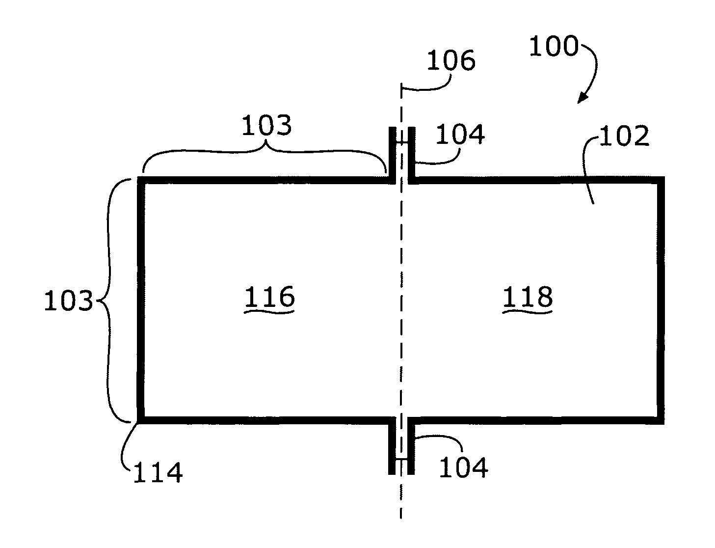
[0014]The present invention relates to a micromachined differential microphone formed by surface micromachining a single surface of a silicon chip.

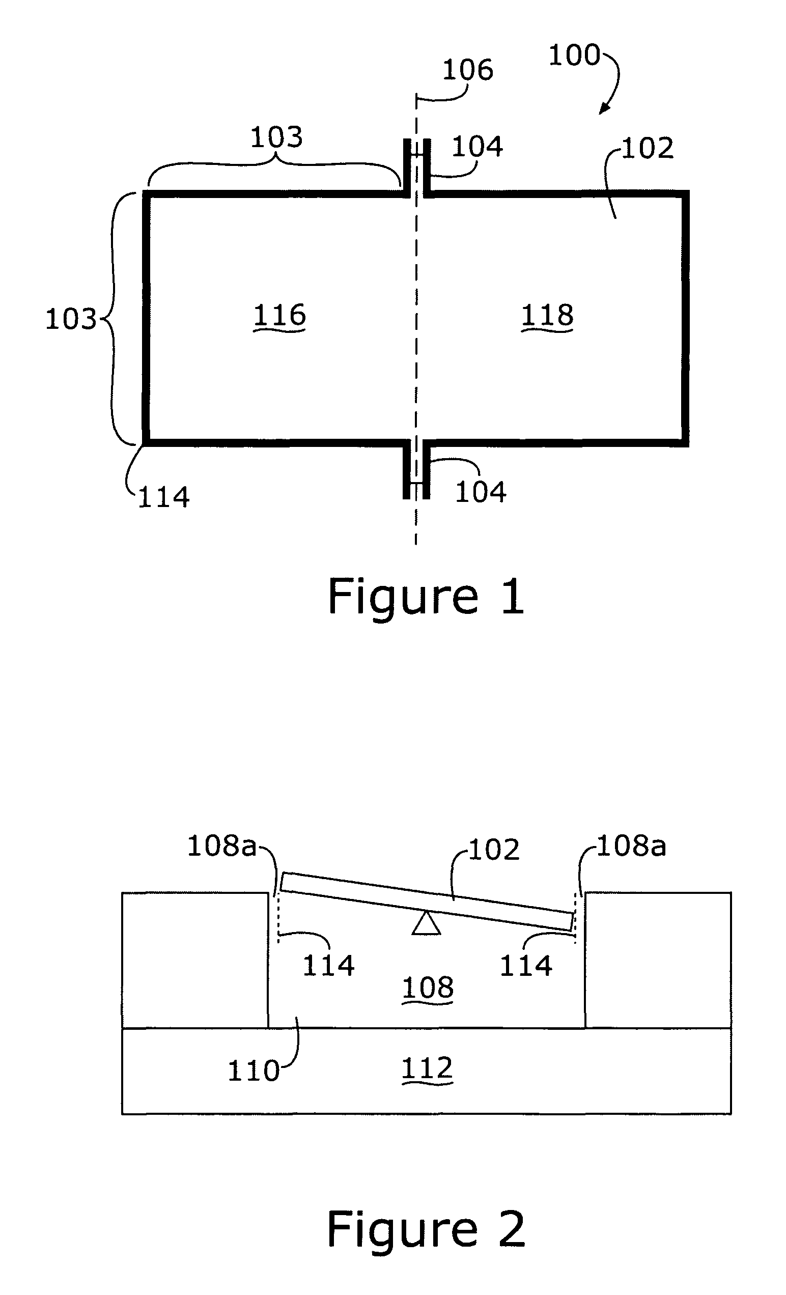
[0015]The motion of a typical microphone diaphragm results in a fluctuation in the net volume of air in the region behind the diaphragm (i.e., the back volume). The present invention provides a microphone diaphragm designed to rock due to acoustic pressure, and hence does not significantly compress the back volume air.

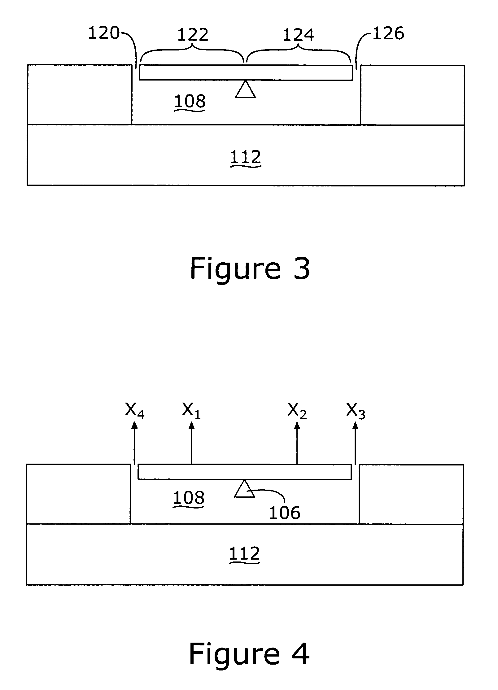
[0016]An analytical model for the acoustic response of the microphone diaphragm including the effects of a slit around the perimeter and the air in the back volume behind the diaphragm has been developed. If the diaphragm is designed to rock about a central pivot, then the back volume and the slit has a negligible effect on the sound-induced response thereof.

[0017]Referring first to FIGS. 1 and 2, there are shown, respectively, a top view of a micromachined microphone diaphragm, including a slit around the perimeter of the d...


PUM


Abstract

A differential microphone having a perimeter slit formed around the microphone diaphragm that replaces the backside hole previously required in conventional silicon, micromachined microphones. The differential microphone is formed using silicon fabrication techniques applied only to a single, front face of a silicon wafer. The backside holes of prior art microphones typically require that a secondary machining operation be performed on the rear surface of the silicon wafer during fabrication. This secondary operation adds complexity and cost to the micromachined microphones so fabricated. Comb fingers forming a portion of a capacitive arrangement may be fabricated as part of the differential microphone diaphragm.

Description

FUNDED RESEARCH[0001]This work is supported in part by the following grant from the National Institute of Health: R01DC005762-03. The Government may have certain rights in this invention.RELATED APPLICATIONS[0002]The present application is related to U.S. Pat. No. 6,788,796 for DIFFERENTIAL MICROPHONE, issued Sep. 7, 2004; and copending U.S. patent application Ser. No. 10 / 689,189 for ROBUST DIAPHRAGM FOR AN ACOUSTIC DEVICE, filed Oct. 20, 2003, and Ser. No. 11 / 198,370 for COMB SENSE MICROPHONE, filed Aug. 5, 2005, all of which are incorporated herein by reference.FIELD OF THE INVENTION[0003]The present invention pertains to differential microphones and, more particularly, to a micromachined, differential microphone absent a backside air pressure relief orifice, fabricatable using surface micromachining techniques.BACKGROUND OF THE INVENTION[0004]In typical micromachined microphones of the prior art, it is generally necessary to maintain a significant volume of air behind the microph...

Claims


Application Information

Patent Timeline
Patent Type & Authority Patents(United States)
IPC IPC(8): H04R31/00
CPCH04R1/38H04R19/005H04R31/00H04R19/04Y10T29/49005Y10T29/49002Y10T29/43Y10T29/4908H01L29/84
Inventor MILES, RONALD N.
Owner THE RES FOUND OF STATE UNIV OF NEW YORK
Why Eureka
Try Eureka