
Hybrid semiconductor circuit with programmable intraconnectivity

Inactive Publication Date: 2006-01-31
GHEEWALA TUSHAR
View PDF6 Cites 60 Cited by
  • Summary
  • Abstract
  • Description
  • Claims
  • Application Information

AI Technical Summary

Benefits of technology

[0012]According to the invention, field programmable circuits and redundant logic are added to the substrate of a hybrid circuit with functionality to bypass unusable dies in order to enhance yield and lower costs of manufacture. In a preferred embodiment, a collar of programmable logic is inserted between the functional component on the hybrid die and its I / O terminals. The programmable logic collar can be programmed after hybrid assembly and test in order to correct assembly errors or die failures through one or more of the following actions: switch between redundant functional units and I / Os on the hybrid die; switch between redundant IC dies on the substrate, invert signal polarity; correct crosstalk errors; perform test and fault isolation. The programmable collar enables repair of defective hybrids without expensive rework, and it reduces the cost of inventorying many IC dies.
[0013]Hybrid circuits according to the invention are an effective alternative to system-on-chip designs because they offer low engineering costs and a wide choice of functionality without the disadvantage of higher production costs due to lower yields and expensive repairs.

Problems solved by technology

However, there are serious cost issues with hybrids which limit their use to niche markets.
Even if a single one of the many ICs on the hybrid fails, it renders the entire hybrid unusable, resulting in low yield and high costs.
Removal and replacement of the defective die is expensive, error-prone and time consuming.
A further disadvantage is that wire bond (and alternates such as solder ball) connections between IC dies and the substrate are large in comparison with on-chip interconnect technologies.
A still further problem is related to the high cost of inventorying IC dies.
However, such attempts have been intended to provide more flexibility in the functionality of the hybrids and are not directed towards solving the manufacturing issues.
However, it does not teach the use of such programmable logic to improve assembly yield or reduce the cost of inventorying the IC dies.
However, there is no teaching of use of such programmable logic to improve assembly yield or to reduce the cost of inventorying the IC dies.
However, the methodology is not applicable to other types of functionalities such as logic.
The prior art also does not teach the use of inclusion of redundant logic and I / Os on the IC die to improve yield and lower costs.

Method used


Image

  • Hybrid semiconductor circuit with programmable intraconnectivity
  • Hybrid semiconductor circuit with programmable intraconnectivity
  • Hybrid semiconductor circuit with programmable intraconnectivity

Examples


Embodiment Construction

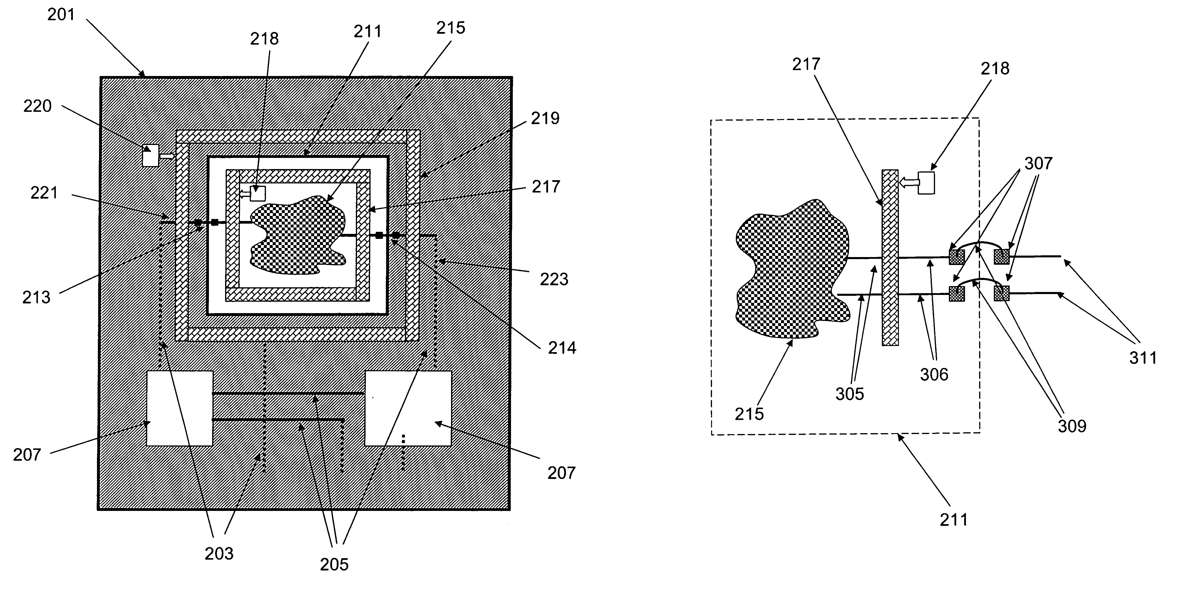
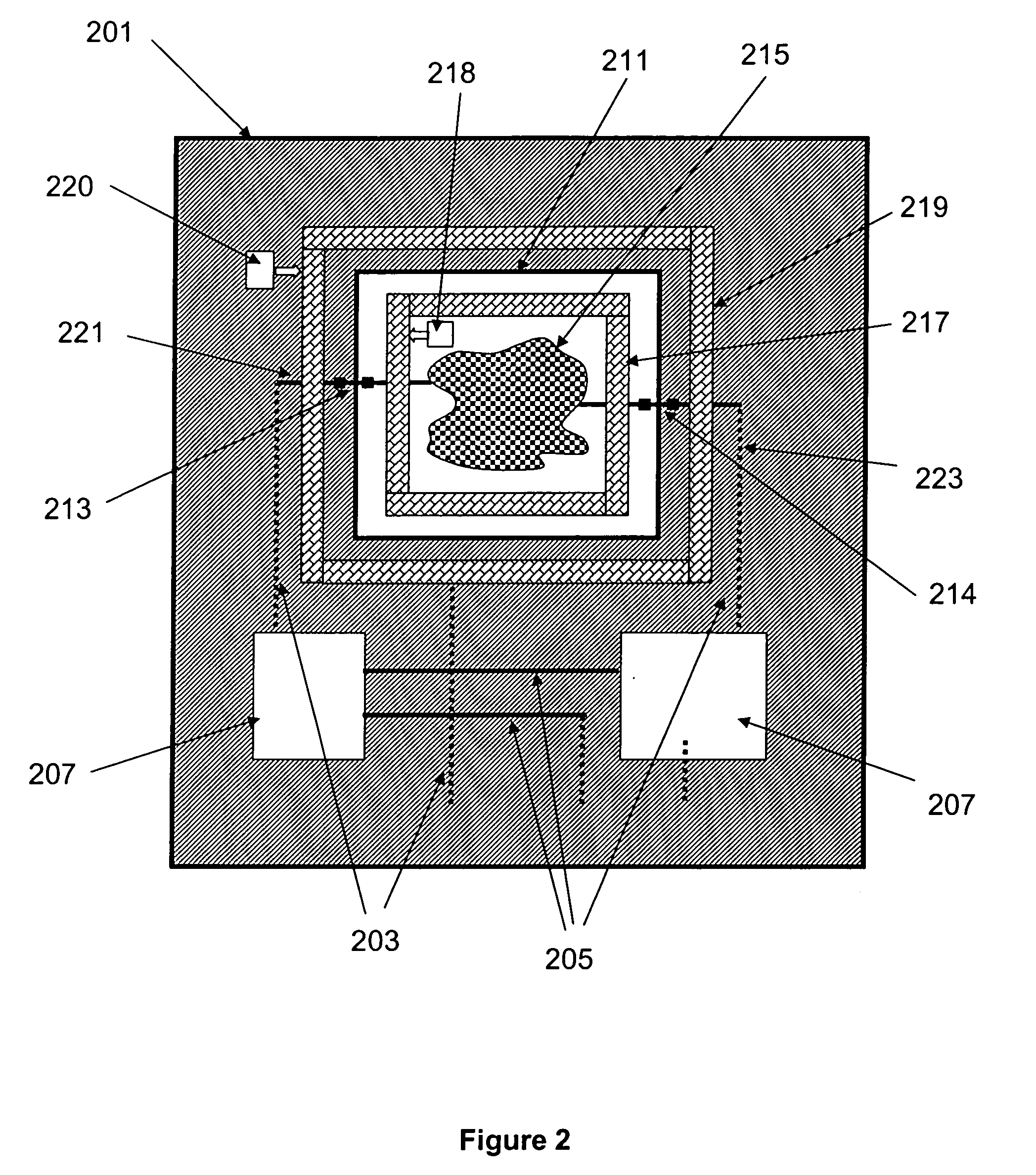
[0024]FIG. 2 illustrates a specific embodiment of the invention in a hybrid substrate 201 comprising interconnect traces 203, 205 and IC dies 207, 211 that have circuits within IC die 211. (The packaging surrounding the hybrid device is not shown for purposes of clarity.) IC dies are electrically connected to the interconnect traces 221, 223 by means of representative wire bonds 213, 214. An embedded functional unit (EFU) 215 is a circuit block that provides the logical functionality of the IC die 211. According to the invention, a programmable logic section 217 is designed into and thus added to the IC die 211 itself. Alternatively, an optional programmable logic section or collar 219 is placed outside of the IC die 211 with direct coupling in between. Further alternatively, the external programmable collar 219 may be used without any internal programmable circuits 217. The programmable logic is controlled by control units 218 and 220 which receive external instructions and use the...


PUM


Abstract

Field programmable circuits and redundant logic are added to the substrate of a hybrid circuit with functionality to bypass and / or repair unusable dies in order to enhance yield and lower costs of manufacture. In a preferred embodiment, a collar of programmable logic is inserted between the functional component on the hybrid die and its I / O terminals. The programmable logic collar can be programmed after hybrid assembly and test in order to correct assembly errors or die failures through one or more of the following actions: switch between redundant functional units and I / Os on the hybrid die; switch between redundant IC dies on the substrate, invert signal polarity; correct crosstalk errors; perform test and fault isolation.

Description

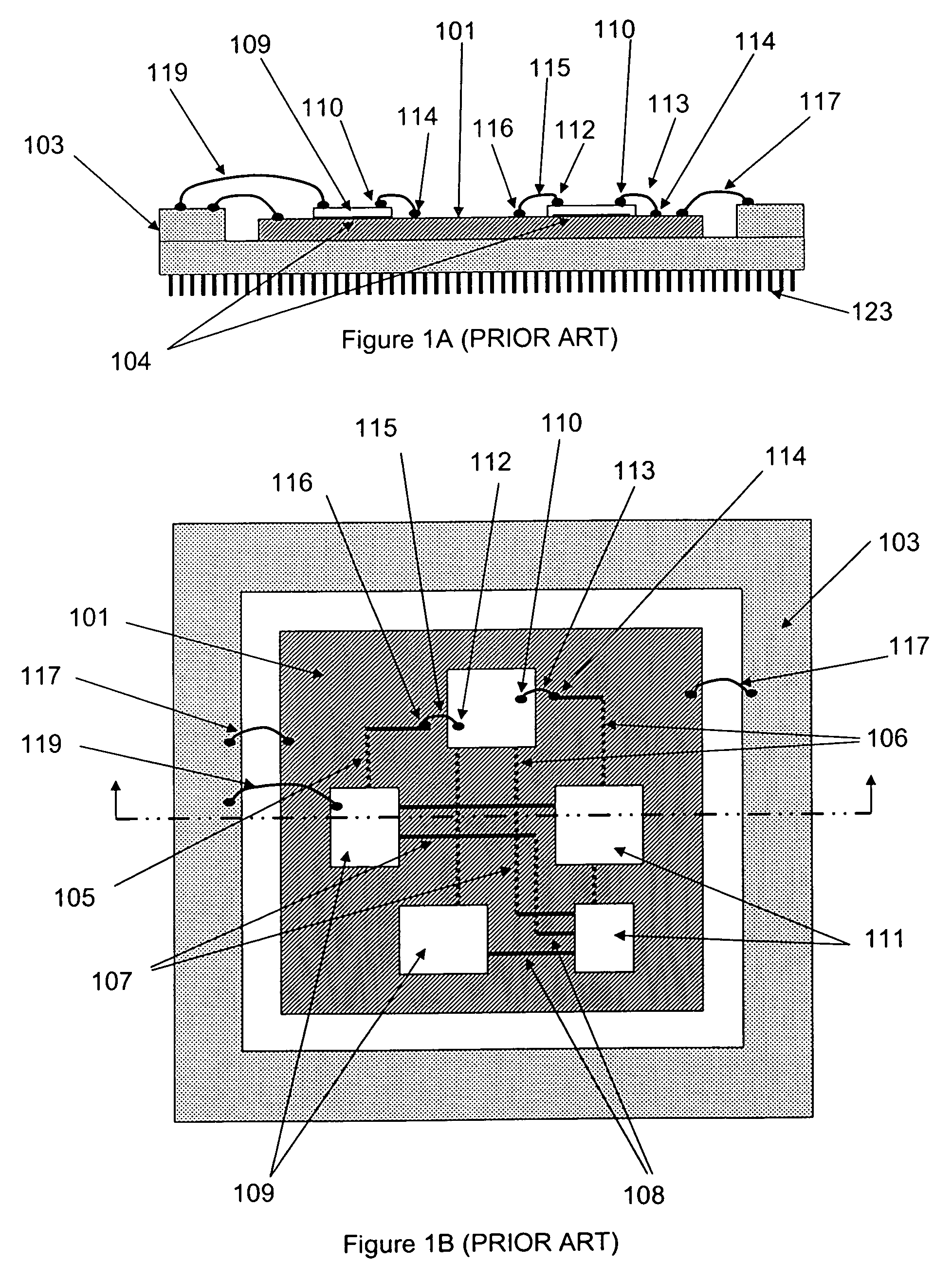
CROSS-REFERENCES TO RELATED APPLICATIONS[0001]NOT APPLICABLESTATEMENT AS TO RIGHTS TO INVENTIONS MADE UNDER FEDERALLY SPONSORED RESEARCH OR DEVELOPMENT[0002]NOT APPLICABLEREFERENCE TO A “SEQUENCE LISTING,” A TABLE, OR A COMPUTER PROGRAM LISTING APPENDIX SUBMITTED ON A COMPACT DISK[0003]NOT APPLICABLEBACKGROUND OF THE INVENTION[0004]This invention relates to the manufacturing techniques for hybrid semiconductor integrated circuits and structures made in accordance with those techniques.[0005]Hybrid circuits have been widely used in the electronic systems industry for over 40 years. FIG. 1A and FIG. 1B illustrate the basic features of a hybrid circuit. It includes a substrate 101 mounted inside an enclosure or package 103, and the substrate 101 has interconnect traces 105–108 in the substrate 101 and integrated circuit (IC) dies 109, 111 on the substrate 101. The IC dies 109, 111 are glued or otherwise bonded to the substrate 101 using a die attach epoxy and electrically connected to ...

Claims


Application Information

Patent Timeline
IPC IPC(8): H01L21/50
CPCH01L23/5382H01L25/0657H01L25/18H01L27/11898H01L2224/48145H01L2225/06506H01L2225/06596H01L2924/10253H01L2924/14H01L2924/1433H01L2924/19041H01L24/48H01L2924/00H01L2224/05554H01L2224/49109H01L2924/00014H01L24/49H01L2224/45099H01L2224/45015H01L2924/207H01L2924/00012
Inventor GHEEWALA, TUSHAR
Owner GHEEWALA TUSHAR
Learn More