
Apparatus and method for increasing the selectivity of FET-based gas sensors

a technology of gas sensors and apparatus, applied in the field of gas sensors, can solve the problems of affecting the usability of applications, affecting the service life of filters, and affecting the detection accuracy of gas sensors, so as to reduce the diffusion rate of analyte gas, reduce the service life of filters, and reduce the effect of operating temperatur

Active Publication Date: 2011-08-09
TDK MICRONAS GMBH
View PDF43 Cites 11 Cited by
  • Summary
  • Abstract
  • Description
  • Claims
  • Application Information

AI Technical Summary

Benefits of technology

[0011]The invention is founded on the recognition that FET-based gas sensors that have a very low operating temperature in contrast with the prior art, for example room temperature, and that are freed of cross sensitivities from interfering gases by preceding in-line filters, are substantially stabilizable with regard to the service life of a sensor. This is accomplished by using fabric-like activated charcoal filters that can be regenerated by a moderate temperature increase, and by limiting the diffusion of the analyte gas, which is made possible by the extremely small amount of gas detectable on the sensitive layer of an FET gas sensor. This is able to substantially increase the service life of filters.
[0012]Advantageously, the sensor effectively eliminates cross sensitivities to increase the detection reliability of gas sensors. In addition, the sensor has long term stability and is relatively economical to build. The sensors make it possible to read weak signals generated by gas-sensitive layers, for example, without the ability of any other stronger gas signals to interfere with the weak signals. Such sensors have operating temperatures between room temperature and about 100° C.

Problems solved by technology

These gas sensors are also subject to the problems of cross sensitivities; in other words, other gases that exist in the application can cause interference with the sensor signal.
Both effects lead to distortion of the desired sensed values and can impair or even prevent usability in an application, depending on the requirement profile.
This approach is not possible with indirect cross sensitivity.
This variant is always associated with distinctly greater effort and higher cost.
The consequences of indirect cross sensitivity, however, cannot be eliminated with this approach, or only with great effort, for example with large sensor arrays or extensive calibration models.
However, it cannot be assumed from this that this is possible for most detection tasks.
This approach is not universally applicable, such that its utility is limited to a few special cases.
They are permeable to the target gas but do not allow gases that cause cross sensitivities to reach the sensor.
However, the filter can become saturated, so that the filter loses its activity and the interfering gas ultimately does reach the sensor and is detected.

Method used


Image

  • Apparatus and method for increasing the selectivity of FET-based gas sensors
  • Apparatus and method for increasing the selectivity of FET-based gas sensors
  • Apparatus and method for increasing the selectivity of FET-based gas sensors

Examples


first embodiment

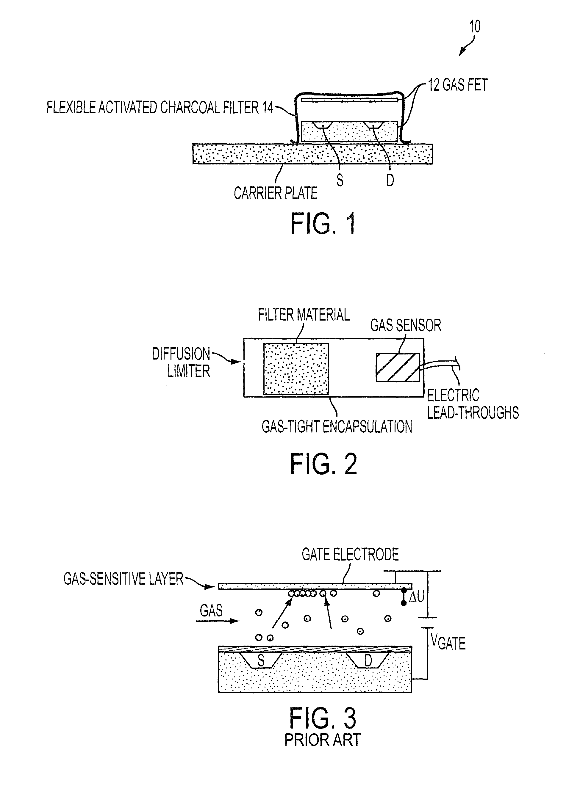
[0025]A first embodiment uses the property of GasFETs that their operating temperatures are drastically lower than those of heated metal oxide sensors, and typically lie between room temperature and about 100° C. In this embodiment, a filter 14 is mounted at only a slight physical distance from the actual sensor element. FIG. 1 illustrates a typical structure. Inasmuch as the operating temperature of the GasFET is about 100° C. at most, as mentioned above, the filter 14 can assume the operating temperature of the GasFET without an unacceptable decrease in its adsorbent activity.

[0026]A suitable filter material is carbon fiber fabric, for example that sold by Charcoal Cloth under the trade name Zorflex™. The fabric is made from pure viscose cellulose that is completely carbonized under appropriate reaction conditions. Because of its structure, the material is distinguished by a large active surface area, with the active surface being produced essentially by the micropores within the ...

second embodiment

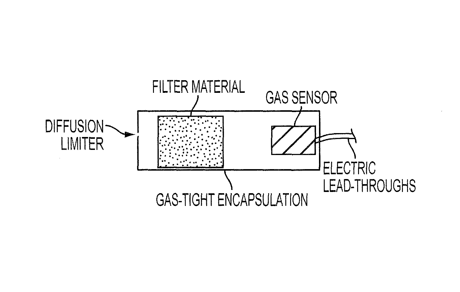
[0029]A second embodiment is based both on structural details of the FET gas sensors and on their property of needing only a very small amount of analyte gas for detection, in contrast to the highly gas-consuming metal oxide sensors. To lengthen the service life of the filter elements and to prevent deactivation from saturation, gas access to the filter element is sharply limited. This greatly delays filter saturation. However, the small amount of available gas is sufficient for gas detection with the FET sensor. FIG. 2 illustrates a schematic description.

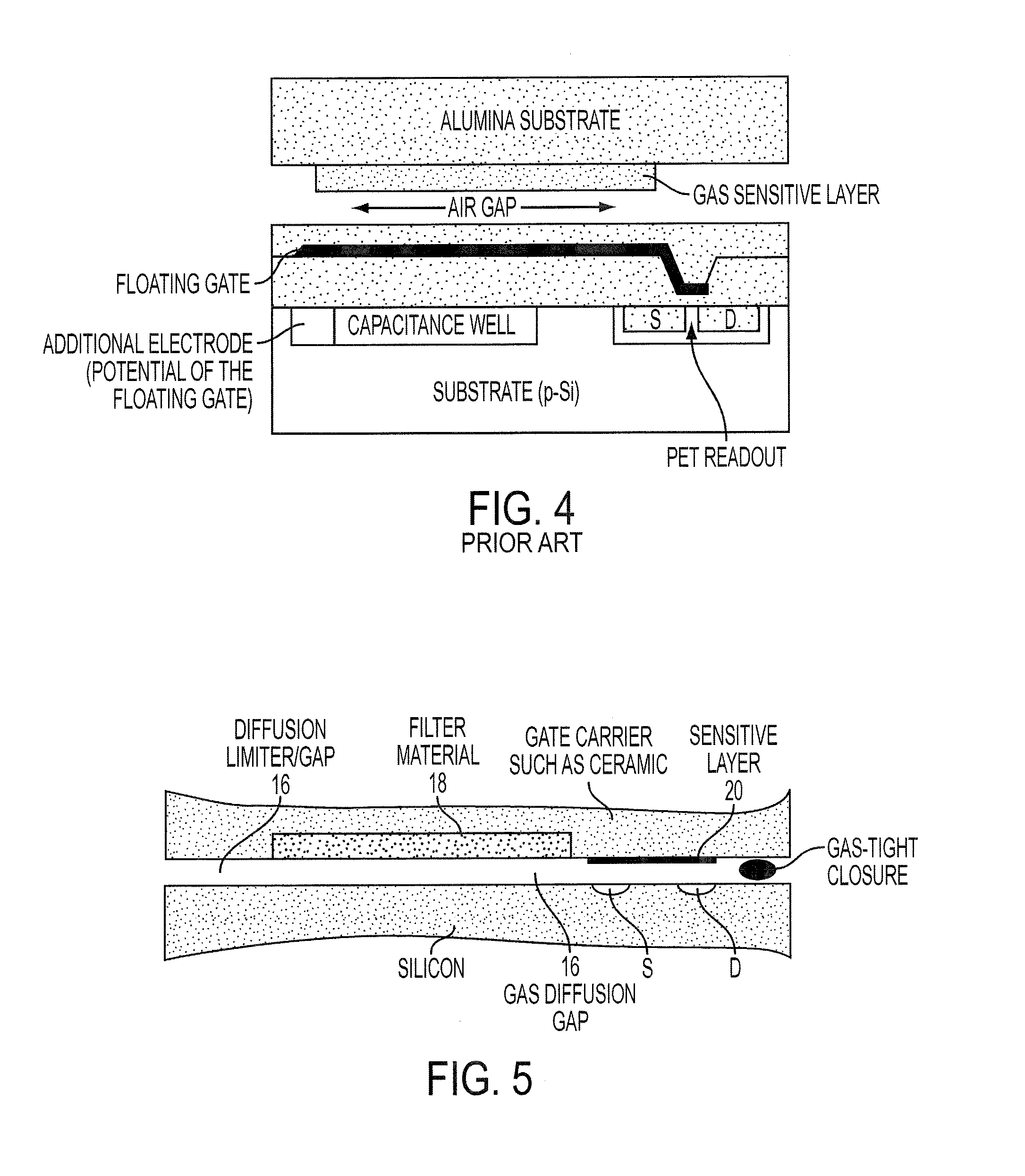
[0030]Gas diffusion can be limited both by a small orifice as a diffusion limiter 16 and by a diffusion-limiting membrane that also protects the system well against dust. An advantageous embodiment of this principle is illustrated in FIG. 5. Illustrated here is the region of the gas diffusion gap 16 in a hybrid flip-chip structure for a gas sensor. A depression is made in the carrier material of the gas-sensitive gate, in which the...


PUM

PropertyMeasurementUnit
temperatureaaaaaaaaaa
operating temperatureaaaaaaaaaa

Abstract

A FET gas sensor having a relatively low operating temperature, for example, room temperature, is free from cross sensitivities from interfering gases by a preceding in-line filter. The sensor's service life is substantially stabilizable by using fabric-like activated charcoal filters which can be regenerated by a moderate temperature increase, and by limiting the diffusion of the analyte gas, which is made possible by the relatively small amount of gas detectable on the sensitive layer of the sensor. This substantially increases the service life of the filters. The gas sensor eliminates cross sensitivities to thereby increase the detection reliability thereof. Also, the gas sensor has relative long term stability and is economical to build. The gas sensor can read relatively weak signals generated by gas-sensitive layers, for example, without other stronger gas signals interfering with the weak signals.

Description

PRIORITY INFORMATION[0001]This patent application claims priority from International patent application PCT / EP2005 / 004281 filed Apr. 22, 2005 and German patent application 10 2004 019 640.0 filed Apr. 22, 2004, which are hereby incorporated by reference.BACKGROUND INFORMATION[0002]This invention relates in general to gas sensors and in particular to a device for increasing the selectivity of gas sensors that employ field effect transistors (“FETs”).[0003]FIGS. 3 and 4 herein and German Patents DE 4239319, DE 19956744, and DE 19956806 disclose FET gas sensors of hybrid construction, which read the work function of a gas-sensitive material using a field effect transistor. These sensors have a number of different applications. On the one hand, they can be operated at ambient temperature, or at slightly elevated temperatures, and they therefore permit low-power operation with batteries or direct connection to data bus lines without the use of auxiliary power. On the other hand, a large ...

Claims


Application Information

Patent Timeline
Patent Type & Authority Patents(United States)
IPC IPC(8): G01N33/00G01N27/414
CPCG01N27/4143G01N33/0014
Inventor FLEISCHER, MAXIMILIANLAMPE, UWEMEIXNER, HANSPOHLE, ROLANDSCHNEIDER, RALFSIMON, ELFRIEDE
Owner TDK MICRONAS GMBH
Learn More