Radiation directional finder and isotope identification system

a technology of isotope identification and radioactivity, applied in the field of radiation detection, can solve the problems of inability of plastic scintillators to perform spectral analysis, inability to identify radiation sources, and high cost of specialized detectors

Inactive Publication Date: 2011-08-09
ADVANCED MEASUREMENT TECH INC +2
View PDF52 Cites 24 Cited by
  • Summary
  • Abstract
  • Description
  • Claims
  • Application Information

AI Technical Summary

Problems solved by technology

However, plastic scintillators do not have the ability to perform spectral analysis.
Therefore, system based on plastic scintillators generally cannot identify the source of radiation, which can be naturally occurring radiation material (NORM).
These specialized detectors are extremely expensive with crystals that cannot be grown to accommodate large surface area detectors.
The Labr3:Ce scintillators have very strong identification capabilities, due to high resolution of Labr3:Ce detectors, but the high cost and limits in available detector crystal sizes makes them unpractical to use.
This means that Labr3:Ce scintillators cannot identify difference between a source in front of detector or with a same angle behind the detector.
The deficiencies of the current systems available do not address the needs of critical security applications.
The current methods for creating directional radiation detectors are too costly, bulky or have heavy weight factors.
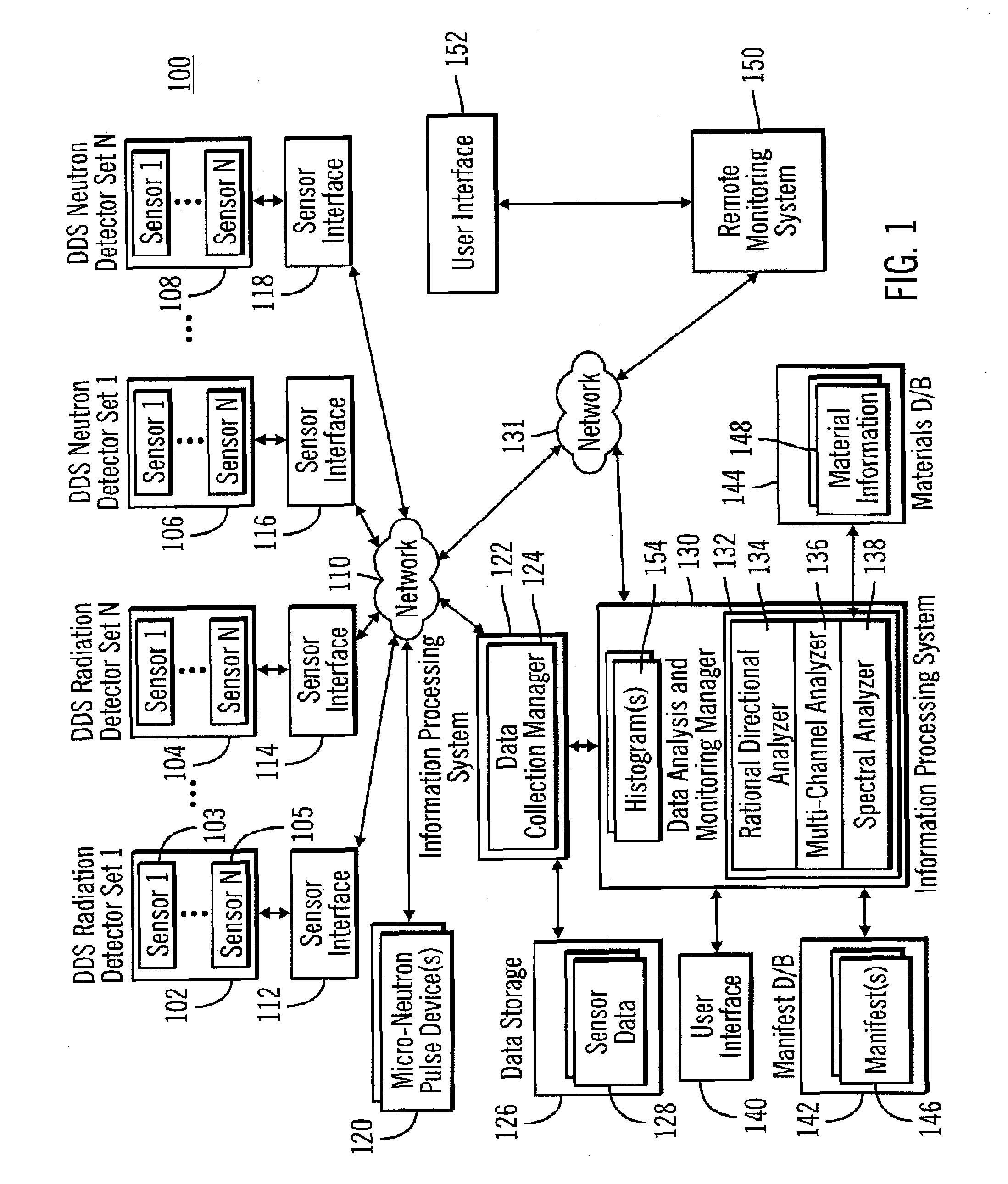
In addition, the current radiation detection methods do not offer a combined stand-off detection, directional finder, position locator, radiation source movement tracking and isotope identification in a cost effective, light weight, and efficient approach that does not require highly specialized detector performance characteristics.

Method used


Image

  • Radiation directional finder and isotope identification system
  • Radiation directional finder and isotope identification system
  • Radiation directional finder and isotope identification system

Examples


Embodiment Construction

[0016]As required, detailed embodiments of the present invention are disclosed herein; however, it is to be understood that the disclosed embodiments are merely examples of the invention, which can be embodied in various forms. Therefore, specific structural and functional details disclosed herein are not to be interpreted as limiting, but merely as a basis for the claims and as a representative basis for teaching one skilled in the art to variously employ the present invention in virtually any appropriately detailed structure. Further, the terms and phrases used herein are not intended to be limiting; but rather, to provide an understandable description of the invention.

[0017]The terms “a” or “an”, as used herein, are defined as one or more than one. The term plurality, as used herein, is defined as two or more than two. The term another, as used herein, is defined as at least a second or more. The terms including and / or having, as used herein, are defined as comprising (i.e., open...


PUM


Abstract

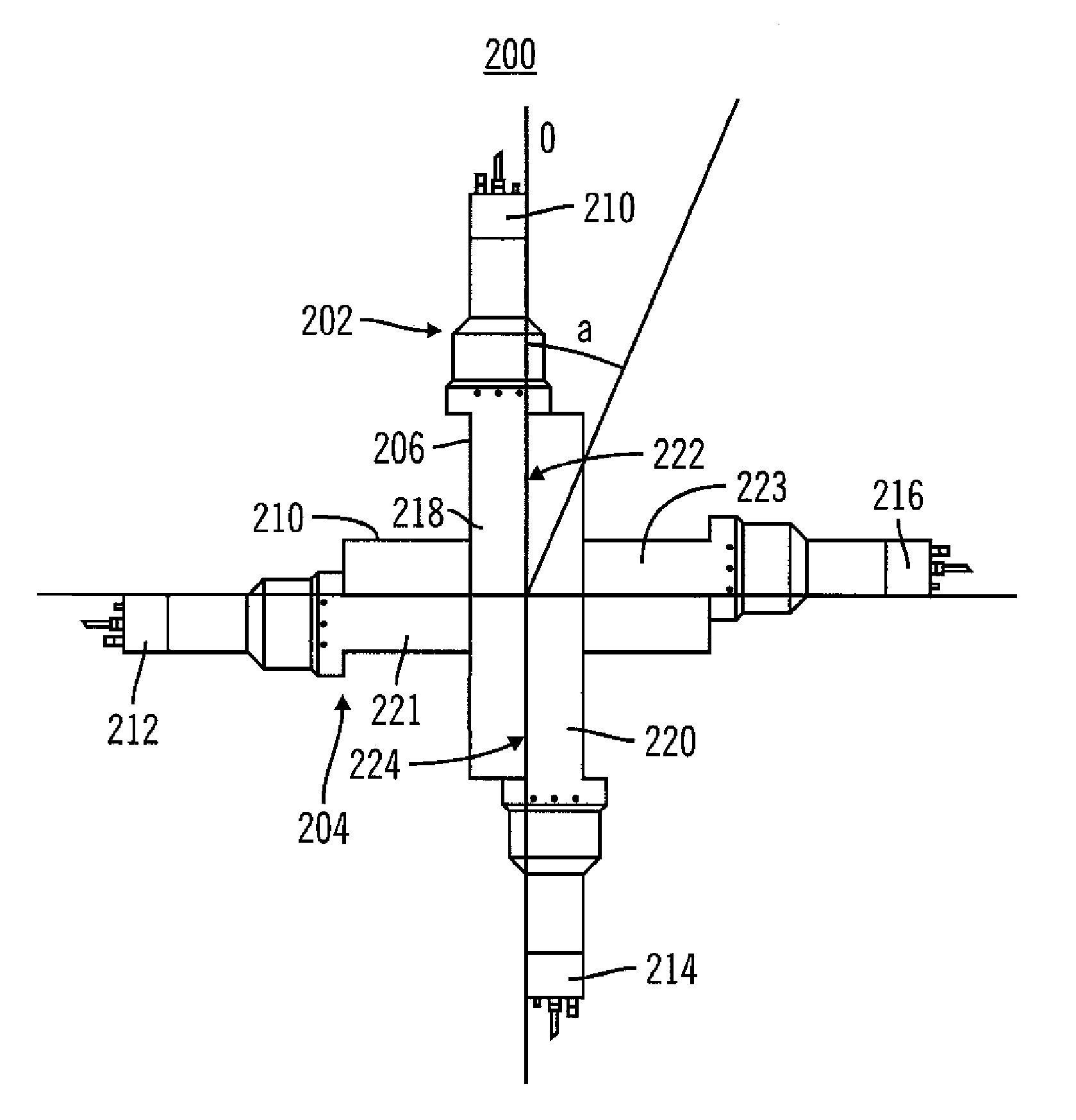
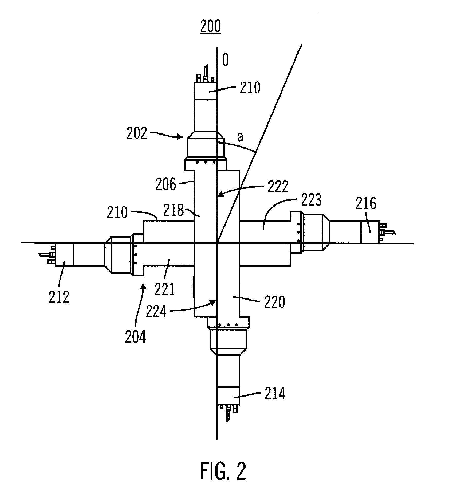
A system and method determine a direction associated with gamma and / or neutron radiation emissions. A first radiation photon count associated with a first detector in a detector set is received from the first detector. The first radiation photon count is associated with at least one radiation source. A second radiation photon count associated with a second detector in the detector set is received from the second detector. The first radiation photon count is compared to the second radiation photon count. One of the first detector and the second detector is identified to have detected a larger number of radiation photons than the other. The at least one radiation source is determined to be substantially in a direction in which the one of the first detector and the second detector that has detected the larger number of radiation photons is facing.

Description

CROSS-REFERENCE TO RELATED APPLICATIONS[0001]This application is based on and claims priority to co-pending provisional U.S. Patent Application No. 61 / 128,114, entitled “Radiation Directional Finder and Isotope Identification System”, filed on May 19, 2008, by the same inventor, and to co-pending U.S. patent application Ser. No. 12 / 409,733, entitled “Mobile Radiation Threat Identification System”, filed on Mar. 24, 2009, by the same inventor, which is based on and claims priority to previously co-pending, and now expired, provisional U.S. Patent Application No. 61 / 070,590, entitled “Marine and Vehicle Mobile Radiation Threat Identification System”, filed on Mar. 24, 2008, by the same inventor, and this application is further based on and claims priority to co-pending provisional U.S. Patent Application No. 61 / 128,115, entitled “Mobile Frame Structure With Passive / Active Sensor Arrays For Non-Invasive Analysis For CBRNE Materials Present”, filed on May 19, 2008, by the same inventor,...

Claims


Application Information

Patent Timeline
Patent Type & Authority Patents(United States)
IPC IPC(8): G01T1/24G01T3/08
CPCG01T1/2907G01T3/08
Inventor FRANK, DAVID L.
Owner ADVANCED MEASUREMENT TECH INC
Why Eureka
Try Eureka