

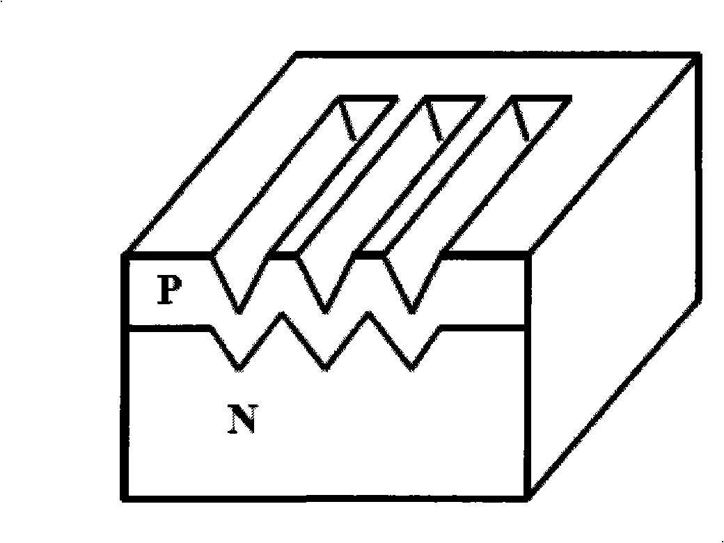
Minisize nuclear battery
A nuclear battery and miniature technology, applied in the field of microelectronics, can solve the problems of reducing energy conversion efficiency, energy loss, etc., and achieve the effect of improving energy conversion efficiency, reducing blocking, and being easy to implement
- Summary
- Abstract
- Description
- Claims
- Application Information
AI Technical Summary
Problems solved by technology
Method used
Image

Examples
Embodiment 1
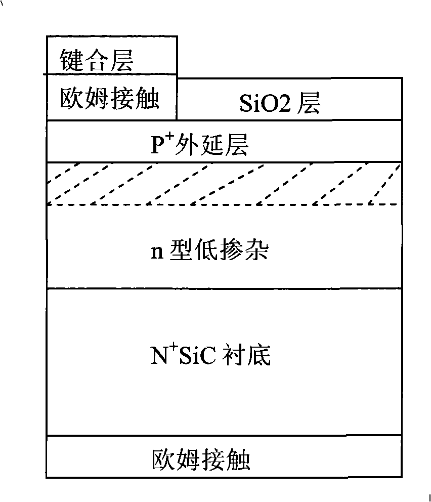
[0047] Step 1. Epitaxial low-doped epitaxial layer on SiC substrate, such as Figure 4 a.
[0048] An N-type highly doped 4H-SiC substrate is selected as the substrate 1. After cleaning, a 4H-SiC low-doped epitaxial layer 2 with a thickness of 10 μm is grown on the epitaxial surface by the low-pressure hot-wall chemical vapor deposition method. The epitaxial growth temperature is 1570° C., the pressure is 100 mbar; the reaction gas is silane and propane; the carrier gas is pure hydrogen.
[0049] Step 2. Form SiO on the epitaxial layer 2 passivation layer, such as Figure 4 b.
[0050] The epitaxy sample is subjected to dry oxygen oxidation for 2 hours at a temperature of 1100±50°C to form a passivation protective layer with a thickness of 25±3nm);
[0051] Step 3. Prepare ohmic contacts on the backside of the substrate, such as Figure 4 c.
[0052] 3.1, using the reactive ion etching method to etch a SiC layer with a thickness of 0.5 μm on the back side of the N-type h...
Embodiment 2
[0062] Steps 1~3 are identical with embodiment 1;
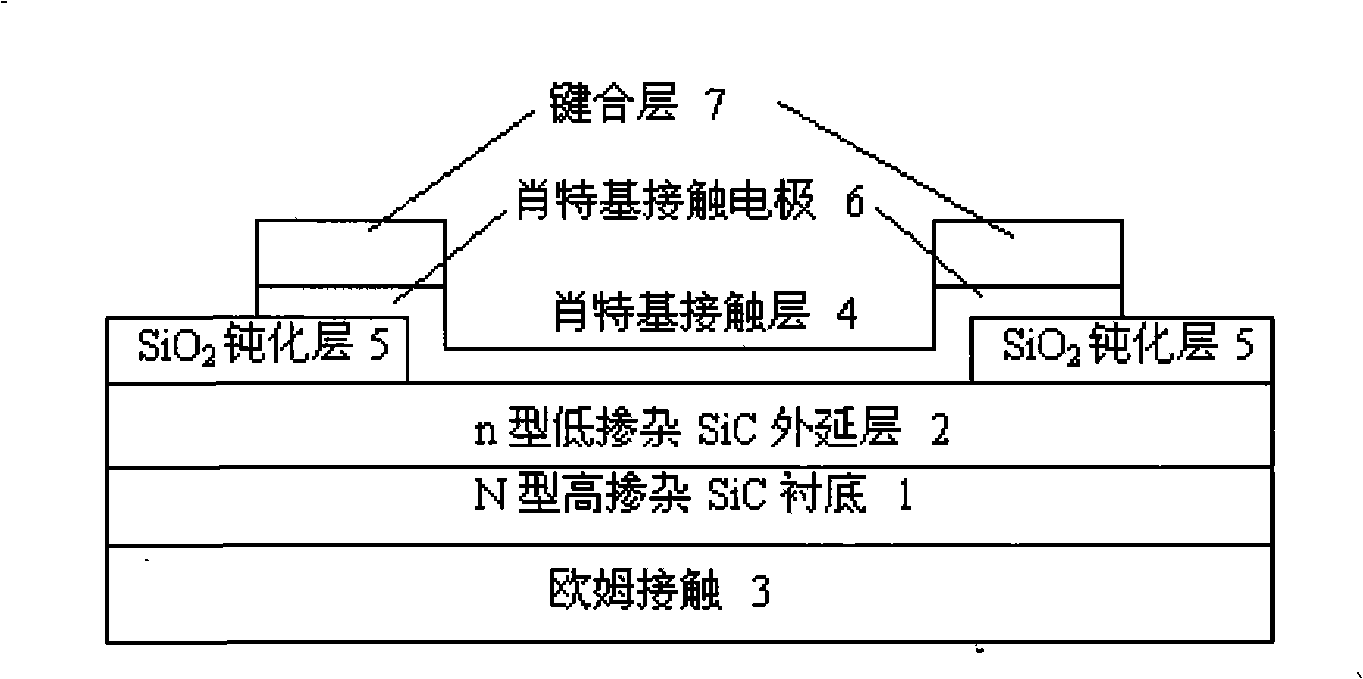
[0063] Step 4. Deposit Schottky contact layer and Schottky electrode, as Figure 4 d.
[0064] 4.1 Use buffered HF acid with a concentration of 5% to etch for 10 seconds, and the SiO 2 A Schottky contact window is etched out in the middle of the passivation layer 5;
[0065] 4.2 SiO on and around the etched window 2 Deposit Ni with a thickness of 20nm on the passivation layer,
[0066] 4.3 Form Schottky metal layers 4 on the windows by ultrasonic stripping, and the SiO around the windows 2 Schottky electrodes 6 are formed on the passivation layer;
[0067] Step 5 is the same as in Example 1.
Embodiment 3
[0069] Steps 1~3 are identical with embodiment 1;
[0070] Step 4. Deposit Schottky contact layer and Schottky electrode, as Figure 4 d.
[0071] 4.1 Use buffered HF acid with a concentration of 5% to etch for 10 seconds, and the SiO 2 A Schottky contact window is etched out in the middle of the passivation layer 5;
[0072] 4.2 SiO on and around the etched window 2 Deposit Ni with a thickness of 12nm on the passivation layer,
[0073] 4.3 Form Schottky metal layers 4 on the windows by ultrasonic stripping, and the SiO around the windows 2 Schottky electrodes 6 are formed on the passivation layer;
[0074] Step 5 is the same as in Example 1.
PUM
 Abstract
Description
Claims
Application Information