Apparatus for transitioning millimeter wave between dielectric waveguide and transmission line

a technology of dielectric waveguide and transmission line, which is applied in the direction of waveguides, resonators, electrical apparatus, etc., can solve the problems of large size and high cost of millimeter-wave communication systems, difficult to design and fabricate the stepped end of standard waveguides, and difficult to use millimeter-wave communication systems for general purposes. , to achieve the effect of simple design, less time and fewer errors

Inactive Publication Date: 2011-08-09
ELECTRONICS & TELECOMM RES INST
View PDF16 Cites 16 Cited by
  • Summary
  • Abstract
  • Description
  • Claims
  • Application Information

AI Technical Summary

Benefits of technology

[0017]In accordance with embodiments of the present invention, a millimeter-wave transition structure can be easily provided using a dielectric waveguide, a transmission line, and a slot formed at a dielectric substrate.
[0018]Furthermore, the millimeter-wave transition apparatus of the present invention can be designed with less time and fabricated with fewer errors.
[0019]In addition, since the millimeter-wave transition apparatus can be simply designed and fabricated, transition losses can be reduced so that the millimeter-wave transition apparatus can have a higher performance.

Problems solved by technology

However, since such millimeter-wave communication systems are fabricated by assembling separate components, the millimeter-wave communication systems are large in size and expensive.
Therefore, it is difficult to use the millimeter-wave communication systems for general purposes.
However, it is difficult to design and fabricate the stepped end of the standard waveguide 110.
As a result, losses increase due to the complicated structure of the standard waveguide 110, and the performance of the millimeter-wave transition apparatus is sensitive to manufacturing errors.

Method used


Image

  • Apparatus for transitioning millimeter wave between dielectric waveguide and transmission line
  • Apparatus for transitioning millimeter wave between dielectric waveguide and transmission line
  • Apparatus for transitioning millimeter wave between dielectric waveguide and transmission line

Examples


Embodiment Construction

[0028]The advantages, features and aspects of the invention will become apparent from the following description of the embodiments with reference to the accompanying drawings, which is set forth hereinafter. Therefore, those skilled in the field of this art of the present invention can embody the technological concept and scope of the invention easily. In addition, if it is considered that detailed description on a related art may obscure the points of the present invention, the detailed description will not be provided herein. The preferred embodiments of the present invention will be described in detail hereinafter with reference to the attached drawings.

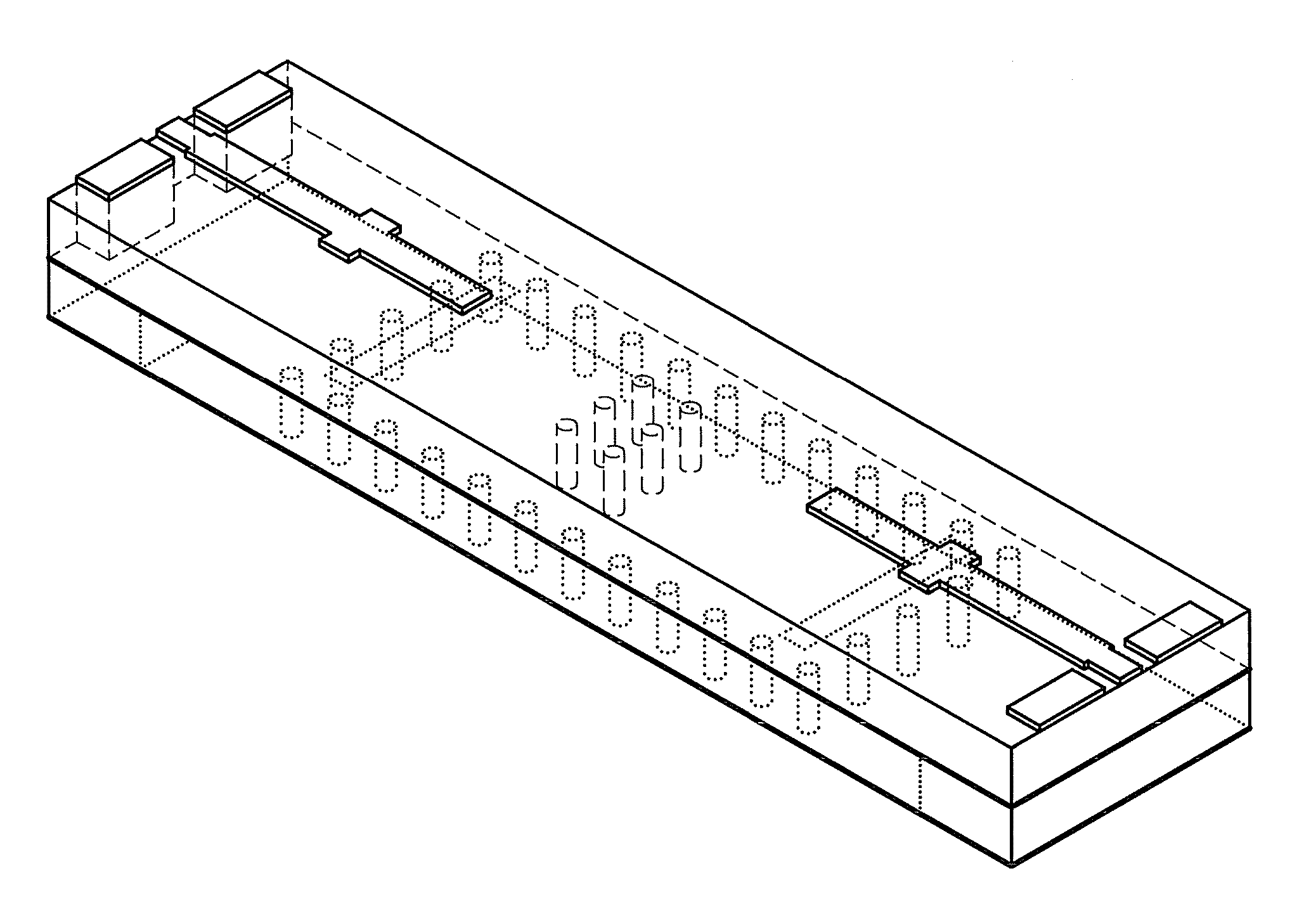
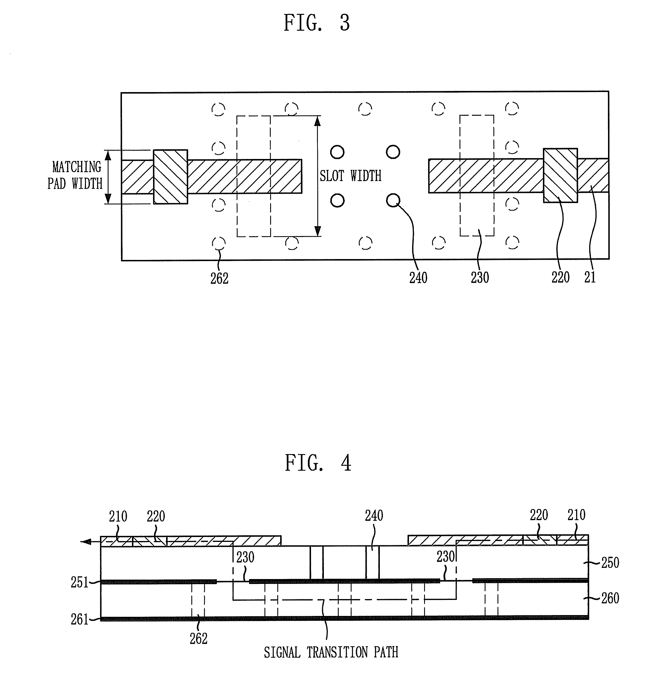
[0029]FIG. 3 is a plan view illustrating an apparatus for transitioning a millimeter wave between a dielectric waveguide and a transmission line in accordance with an embodiment of the present invention, and FIG. 4 is a cross-sectional view illustrating the millimeter-wave transition apparatus of FIG. 3.

[0030]Referring to FIGS. 3 ...


PUM


Abstract

Provided is an apparatus for transitioning a millimeter wave between dielectric waveguide and transmission line using a millimeter wave transition structure formed by the dielectric waveguide, the transmission line, and a slot to transition a signal with lower losses. The apparatus includes: transmission lines disposed respectively at input and output terminals on an uppermost dielectric substrate in a signal transition direction and adapted to transition a signal; a dielectric waveguide formed by a via array disposed between top and bottom ground surfaces of a lowermost dielectric substrate in the signal transition direction as a signal transition path; and slots disposed at a signal transition path of an upper ground surface of each dielectric substrate to connect the transmission lines to the dielectric waveguide so as to transition a signal from the transmission line of the input terminal to the transmission line of the output terminal through the dielectric waveguide.

Description

CROSS REFERENCE TO RELATED APPLICATIONS[0001]This application claims the benefit under 35 U.S.C. Section 371, of PCT International Application PCT / KR2007 / 005367 filed Oct. 30, 2007, which claimed priority to Korean Application 10-2006-0114045 filed Nov. 17, 2006, and Korean Application 10-2007-0078569 filed Aug. 6, 2007 in the Korean Intellectual Property Office, the disclosures of all of which are hereby incorporated by reference.TECHNICAL FIELD[0002]The present invention relates to an apparatus for transitioning a millimeter wave between a dielectric waveguide and a transmission line; and, more particularly, to an apparatus for transitioning a millimeter wave between a dielectric waveguide and a transmission line using a millimeter wave transition structure formed by the dielectric waveguide, the transmission line, and a slot so as to transition a signal with lower losses.[0003]This work was supported by the Information Technology (IT) research and development program of the Korea...

Claims


Application Information

Patent Timeline
Patent Type & Authority Patents(United States)
IPC IPC(8): H01P1/20
CPCH01P3/121H01P5/107H01P3/08H01P3/16H01P3/02
Inventor KIM, BONG-SUBYUN, WOO-JINKIM, KWANG-SEONSONG, MYUNG-SUN
Owner ELECTRONICS & TELECOMM RES INST
Why Eureka
Try Eureka