Adjustable locking windage and elevation knob

a technology of locking windage and elevation knob, which is applied in the direction of mechanical control devices, instruments, process and machine control, etc., can solve the problems of assembly being easily knocked out of position, the illumination reticle to turn off or the scope to become unfocused at an inopportune time, and the time and inconvenience of having to remove the dust cap, etc., to achieve the effect of simple formation

Active Publication Date: 2011-08-16
PLASTICAN +1
View PDF14 Cites 58 Cited by
  • Summary
  • Abstract
  • Description
  • Claims
  • Application Information

AI Technical Summary

Benefits of technology

[0006]The inventive structure presents a number of advantages over the prior art. First, the invention is simple to form. The adjustment knob assembly may be attached to a scope or other sighting mechanism and may be adapted to conventional adjustment mechanisms through integral or aftermarket manufacture. In the preferred embodiment, a rubber washer and / or any other weather resistant material and / or sealant is placed between the turret and the adjustment knob assembly creating a weather resistant seal to prevent environmental elements from causing damage to the interior of the scope.
[0007]In the preferred embodiment, a turn knob is placed over the adjustment knob assembly. Within the turn knob is a knurl knob and a lock down nut, or a similar locking mechanism. The knurl knob fits above the lock down nut. In the preferred embodiment, the knurl knob has a hollow groove in the side of the knurl knob, which is capable of receiving a pin. Once the turn knob is in place, a pin is inserted through the turn knob and into the hollow groove in the knurl knob, which allows the turn knob to pull and push the knurl knob without the two pieces disengaging. When the turn knob is pushed down, the turn knob engages the annular grooves on the lock down nut preventing the knurl knob and turn knob from rotating or making any undesired adjustments. When the turn knob is pulled up, the turn knob is disengaged from the lock down nut and the knurl knob and turn knob may rotate freely to make desired adjustments until pushed back down, locking the knurl knob and turn knob into position.

Problems solved by technology

However, because gravity and wind play a role in the trajectory of a bullet by causing the bullet to drop and / or drift to one side of the intended target, hunters have to make adjustments to the scope to account for these effects.
Problems with these types of assemblies include the time and inconvenience of having to remove the dust cap and the necessity of utilizing a small screwdriver or similar device to effectuate adjustments.
However, the drawback to this adjustment assembly is that the assembly may be easily knocked out of position and is not designed for field use where a sturdy and weather resistant adjustment assembly is a necessity.
The cited art knob may be knocked out of position easily; thus causing the illuminated reticle to turn off or the scope to become unfocused at an inopportune time, such as when attempting to shoot a target.

Method used


Image

  • Adjustable locking windage and elevation knob
  • Adjustable locking windage and elevation knob
  • Adjustable locking windage and elevation knob

Examples


Embodiment Construction

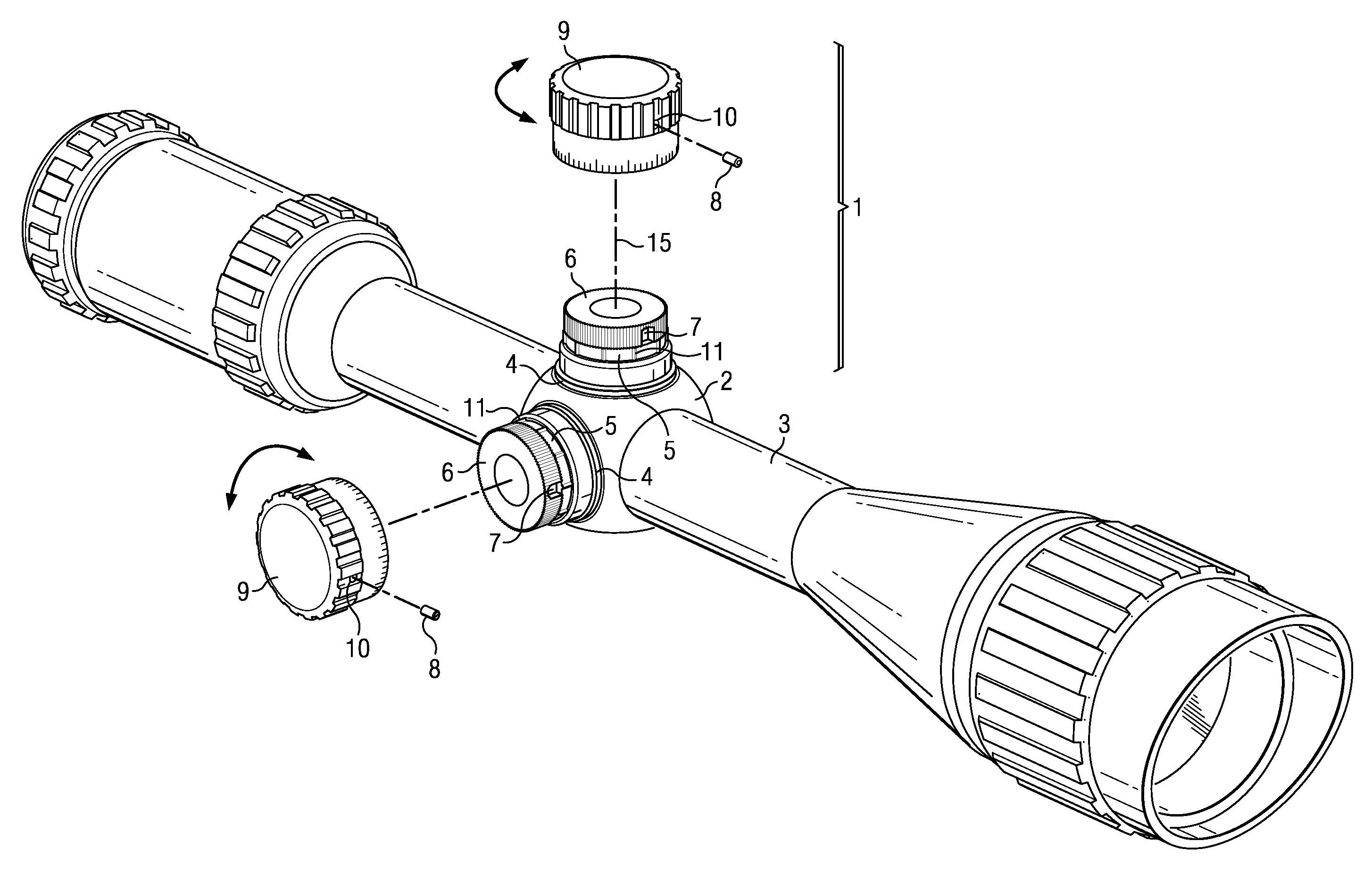
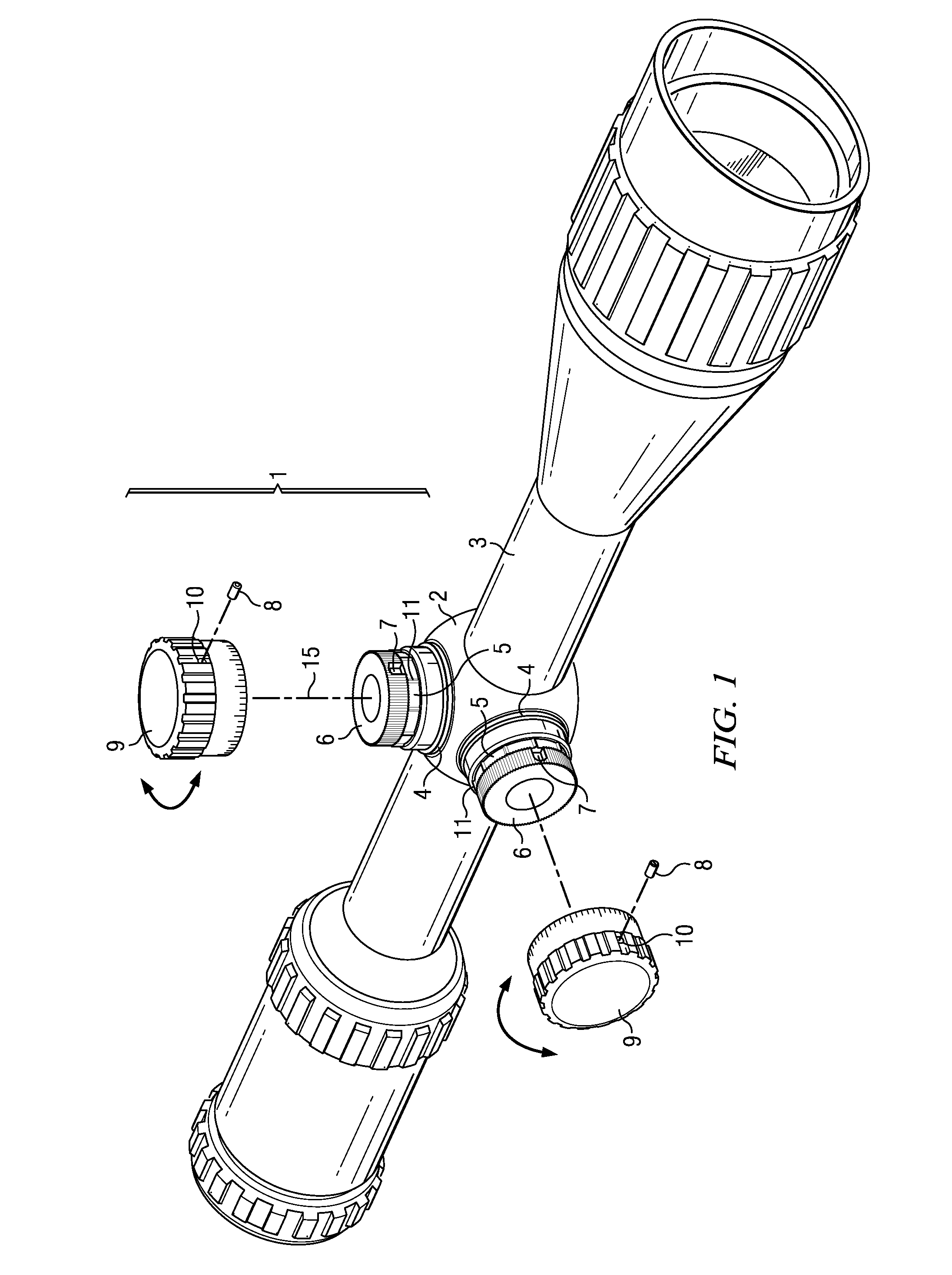
[0017]Shown in FIG. 1 is an adjustment knob assembly 1 attached to a turret 2 of a scope 3. A rubber washer 4 is placed between the turret 2 and the adjustment knob assembly 1 to create a weatherproof seal between the turret 2 and the adjustment knob assembly 1. A knurl knob 6 is placed above the lock down nut 5. The knurl knob 6 has a hollow groove 7 on its side for receiving a pin 8. A turn knob 9 is placed over the knurl knob 6 and lock down nut 5 to form the adjustment knob assembly 1, as shown in FIG. 1, wherein the turn knob 9, the knurl knob 6, and the lock down nut 5 of adjustment knob assembly 1 are aligned along a longitudinal axis 15.

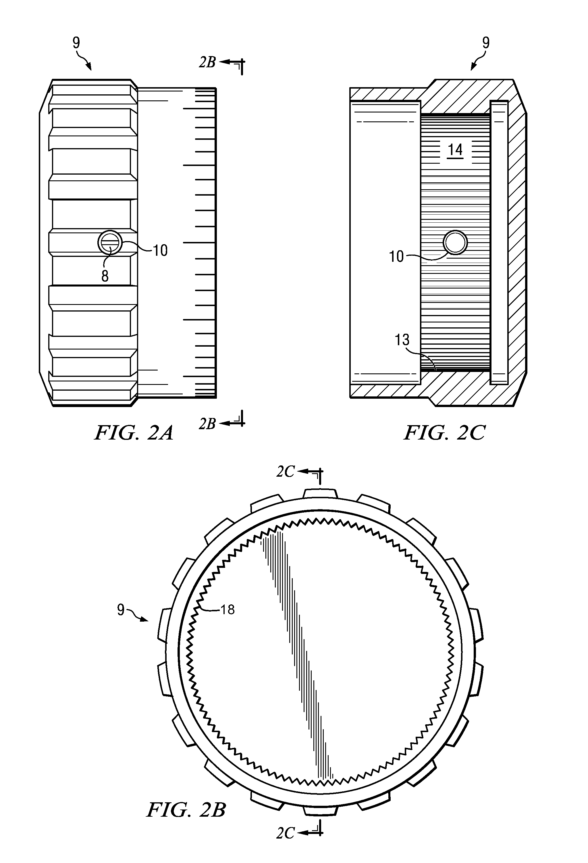
[0018]Once the turn knob 9 is placed over the knurl knob 6 and the lock down nut 5, a pin 8 is placed through hole 10 in turn knob 9. The hollow groove 7 on the side of the knurl knob 6 receives pin 8, which prevents the knurl knob 6 and turn knob 9 from disengaging during the push-pull movement.

[0019]When the turn knob 9 is pushed down over ...


PUM


Abstract

A novel, adjustable locking windage and elevation knob assembly for the improved accuracy of scopes wherein an adjustment turn knob may be raised from its locked position to rotate freely for desired windage or elevation adjustments and thereafter be pushed back down into a locked position.

Description

FIELD OF THE INVENTION[0001]This invention relates to the design and construction of a novel, adjustable locking windage and elevation knob assembly for the improved accuracy of scopes.BACKGROUND OF THE INVENTION[0002]Scopes, particularly those used for hunting, are well known in the prior art. Scopes are generally used to assist hunters in aiming at desired targets. However, because gravity and wind play a role in the trajectory of a bullet by causing the bullet to drop and / or drift to one side of the intended target, hunters have to make adjustments to the scope to account for these effects. Moreover, as the effect of gravity and wind drift on a bullet's trajectory will vary depending upon the distance to the target, multiple adjustments may be necessary at a shooting range or in the field to account for these variances.[0003]To address the above and other related scope adjustment and performance issues, the prior art has developed to include various adjustment knob assemblies. Mo...

Claims


Application Information

Patent Timeline
Patent Type & Authority Patents(United States)
IPC IPC(8): G05G1/10F41G1/38G02B23/00
CPCF41G1/44G05G1/10Y10T74/2084F41G1/38
Inventor CASAS, JUAN CARLOS
Owner PLASTICAN
Why Eureka
Try Eureka