Flat push coke wet quenching apparatus and process

a technology of wet quenching apparatus and coke, which is applied in the direction of chemistry apparatus and processes, separation processes, and dispersed particle separation, etc., can solve the problems of large amount of coke dust created, and the available pressure drop of high-efficiency removal of particulate matter, and achieves reduced particulate matter generation, reduced structure and equipment requirements, and high dust collection efficiency

Inactive Publication Date: 2011-08-16
SUNCOKE TECH & DEV LLC
View PDF13 Cites 74 Cited by
  • Summary
  • Abstract
  • Description
  • Claims
  • Application Information

AI Technical Summary

Benefits of technology

[0008]The method and apparatus described above provide unique advantages for coking operations. In particular, flat pushing of the coke onto a quench car as a unitary slab of incandescent coke may significantly reduce an amount of particulate matter generated during a coke oven discharge operation. Accordingly, dust collection equipment for collecting particulate matter during the coke discharge operation may be substantially smaller and may provide higher dust collection efficiencies. Another advantage of the method and apparatus disclosed herein may be the simplicity of operation and the elimination of structures and equipment necessary to quench the coke and handle the quenched coke product. For example, the dust collection system has no moving parts and may rely only on pressure generated in a substantially enclosed chamber as a motive force for gas flow through the dust collection system.

Problems solved by technology

One of the problems associated with the coke making process is dusting problems associated with removing the hot coke from the oven and dropping the coke into a quenching car as the coke is discharged from the coke ovens.
As the coke drops into the quenching car, a significant amount of coke dust is created.
However, many of these systems rely on pressure drop through a device, such as baffles or multi-cyclones to obtain efficient particulate removal.
However, conventional quench systems have very little available pressure drop available for high efficiency removal of particulate matter.

Method used


Image

  • Flat push coke wet quenching apparatus and process
  • Flat push coke wet quenching apparatus and process
  • Flat push coke wet quenching apparatus and process

Examples


Embodiment Construction

:

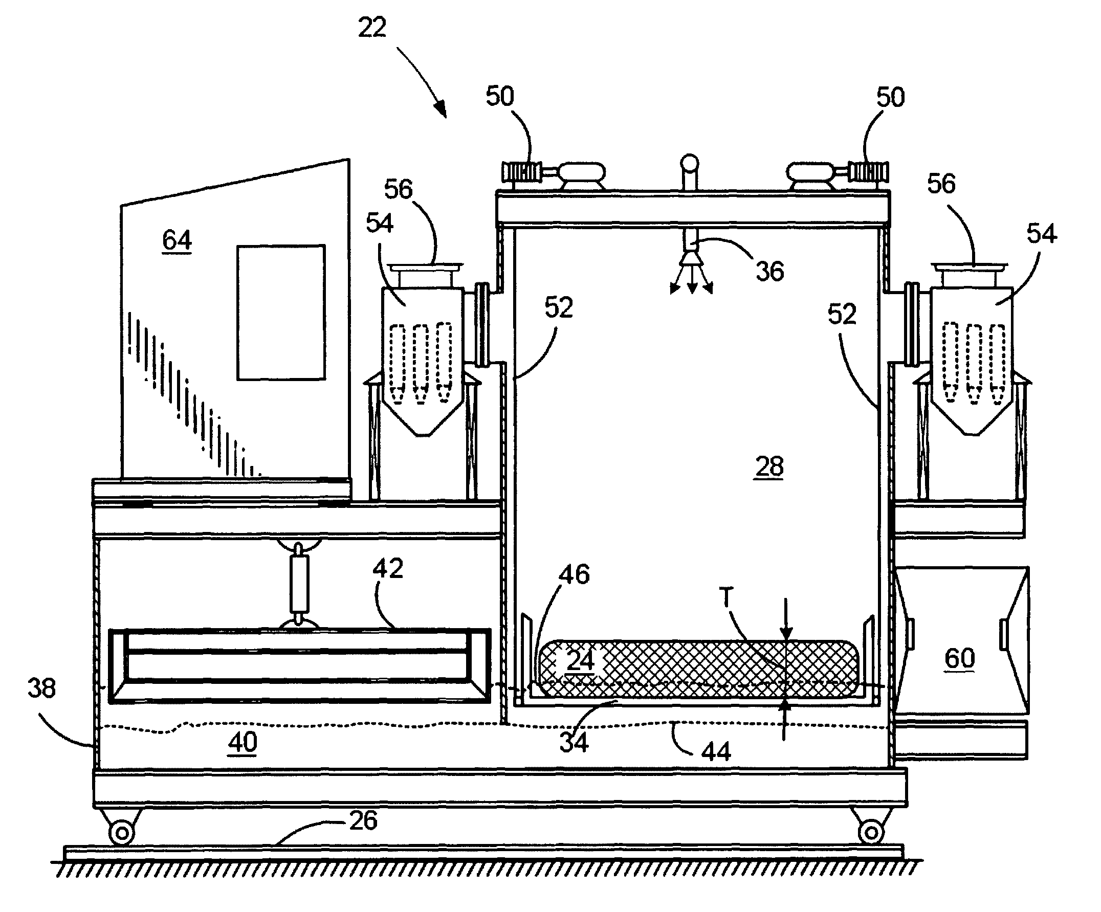
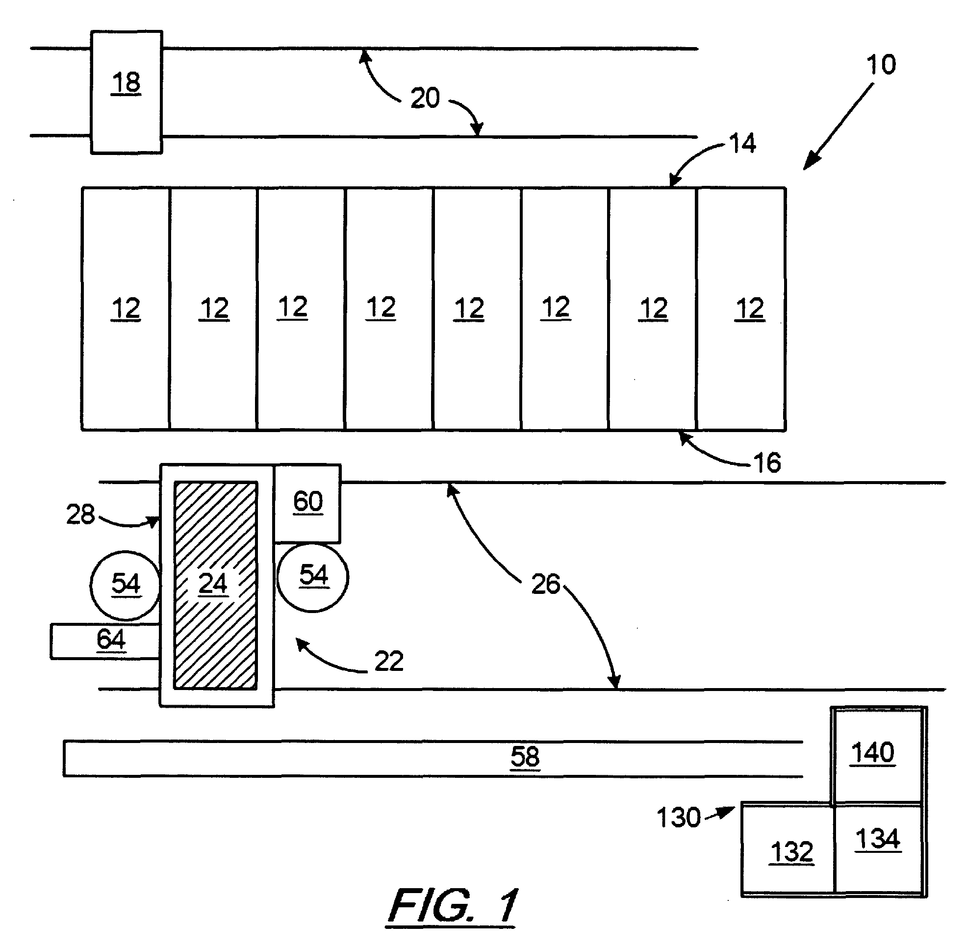
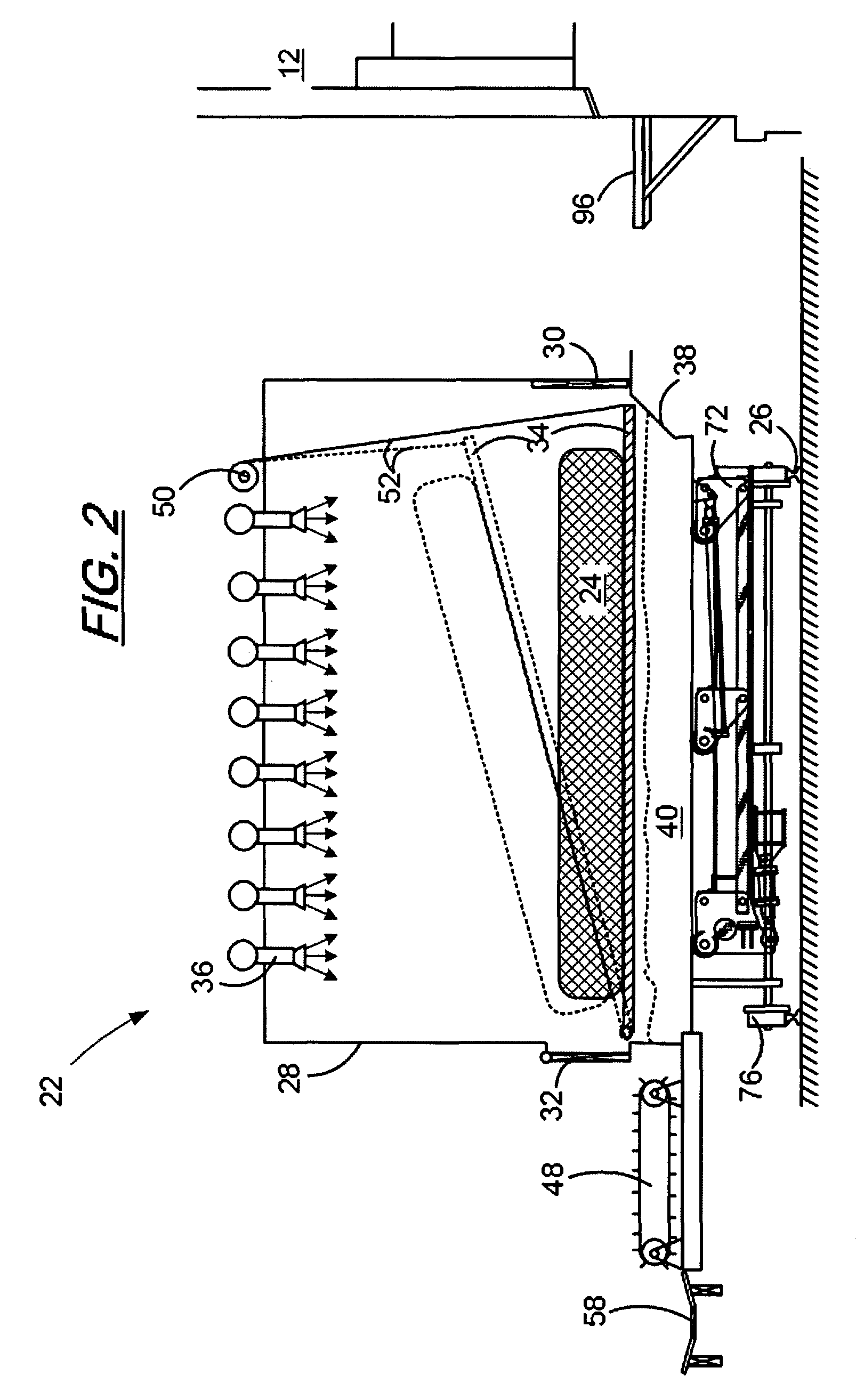
[0023]For purposes of this disclosure, a “unitary slab of coke” is intended to include fused incandescent coke structures as made in a coking oven. The unitary slabs of coke may have sizes ranging from about a meter wide to tens of meters long and up to about 1.5 meters deep and may weigh between about 20 and about 40 metric tons. With reference to FIG. 1, there is illustrated a plan schematic view of a coke oven battery 10 and associated equipment for charging a coke oven battery and for removing and quenching coke produced in the coke oven battery 10 according to an exemplary embodiment of the disclosure. The typical coke oven battery 10 contains a plurality of side by side coke ovens 12. Each of the coke ovens 12 has a coal inlet end 14 and a coke outlet end 16 opposite the inlet end 14.

[0024]A typical coal coking cycle may range from 24 to 48 hours or more depending on the size of the coal charge to the coke ovens 12. At the end of the coking cycle, the coke is pushed out of th...


PUM

PropertyMeasurementUnit
angleaaaaaaaaaa
temperatureaaaaaaaaaa
sizesaaaaaaaaaa

Abstract

A method and apparatus for quenching metallurgical coke made in a coking oven. The method includes pushing a unitary slab of incandescent coke onto a substantially planar receiving surface of an enclosed quenching car so that substantially all of the coke from the coking oven is pushed as a unitary slab onto the receiving surface of the quenching car. The slab of incandescent coke is quenched in an enclosed environment within the quenching car with a plurality of water quench nozzles while submerging at least a portion of the slab of incandescent coke by raising a water level in the quenching car. Subsequent to quenching the coke, the planar receiving surface is tilted to an angle sufficient to slide the quenched coke off of the planar receiving surface and onto a product collection conveyer and sufficient to drain water from the quenched coke.

Description

FEILD[0001]The disclosure relates to a method and apparatus for producing coke from coal and in particular to an apparatus and method for wet quenching of a flat pushed incandescent slab of metallurgical coke in a single, multipurpose apparatus.BACKGROUND AND SUMMARY[0002]Metallurgical coke is a solid carbon fuel and carbon source used to melt and reduce iron ore in the production of steel. During an iron-making process, iron ore, coke, heated air and limestone or other fluxes are fed into a blast furnace. The heated air causes combustion of the coke which provides heat and a source of carbon for reducing iron oxides to iron. Limestone or other fluxes may be added to react with and remove the acidic impurities, called slag, from the molten iron. The limestone-impurities float to the top of the molten iron and are skimmed off.[0003]In one process, known as the “Thompson Coking Process,” coke used for refining metal ores is produced by batch feeding pulverized coal to an oven which is...

Claims


Application Information

Patent Timeline
Patent Type & Authority Patents(United States)
IPC IPC(8): C10B39/04
CPCC10B39/14C10B39/04C10B39/12B01D45/12C10B39/18C10B45/00
Inventor BARKDOLL, MICHAEL P.
Owner SUNCOKE TECH & DEV LLC
Why Eureka
Try Eureka