Optical disc recording/reproducing apparatus

a technology of optical discs and control signals, applied in the field of optical disc recording/reproducing apparatuses, can solve problems such as learning accuracy, and achieve the effects of reducing the analog circuit scale, reducing the size of the chip, and improving detection accuracy

Inactive Publication Date: 2011-08-16
PANASONIC SEMICON SOLUTIONS CO LTD
View PDF9 Cites 2 Cited by
  • Summary
  • Abstract
  • Description
  • Claims
  • Application Information

AI Technical Summary

Benefits of technology

[0028]According to the present invention, an optical disc recording / reproducing apparatus comprises: an optical pickup which applies a spot of light beam to an optical disc of a land / groove recording system including a first header region that is formed at a position shifted toward one side of a direction perpendicular to a track and a second header region that is formed at a position shifted toward the opposite side from the first header region, and detects reproduced signals from the reflected light beam; a first adder which adds the reproduced signals detection by the optical pickup; a variable amplifier which performs amplitude adjustment for a header region of the added reproduced signal; an offset voltage adjustment circuit which performs adjustment so that the signal in the amplitude-adjusted header region falls within a dynamic range; an A / D converter which converts the output signal from the variable amplifier into a digital signal; peak detection circuits which detect peak values of the reproduced signals in a first section and a second section in the header region, respectively; bottom detection circuits which detect bottom values of the reproduced signals in the first section and the second section in the header region, respectively; a first subtracter which obtains amplitude information in the first section and the second section in the header region, from the peak values and the bottom values which are detected in the first section and the second section by the respective detection circuits; a second subtracter which obtains a difference in amplitude between the first section and the second section in the header region, based on the amplitude information obtained by the first subtracter, and outputs the amplitude difference as an off-track error signal; a detection control timing generation circuit which generates a detection control timing for a detection section that the first section or the second section in the header region, and replaces the detection control timings of the respective detection circuits at a switching between the land and the groove; wherein the respective detection circuits hold the detected values obtained by the previous detection operations in sections other than the detection section under the control of the detection control timing generation circuit. Therefore, the analog circuit scale can be significantly reduced by replacing the processings which have conventionally been performed by the analog circuits with digital processings, thereby realizing a reduction in the chip size using the high-miniaturization process.
[0029]Further, since the responsiveness which is not likely to follow noises can be realized while ensuring the follow-up performance, detection accuracy can be ensured against a signal of poor S / N ratio. Further, since holding of the detected values is performed by digital processing, advanced performance can be realized. Furthermore, since the detection variation is reduced, the detection accuracy can be enhanced by increasing the frequency band of the off-track error signal averaging process, thereby responding to a high-rate speed.
[0030]Furthermore, since the detection operation is controlled to be held when an irregular gate signal such as an ID gate signal deviating from the actual address position on the time axis is generated or when a defect such as a dropout occurs, the detection error can be minimized.
[0031]Furthermore, since the error factors such as variations of the pickup and the analog circuit and differences between the inner and outer circumferences can be absorbed by performing the offset control and the gain control for the detected values from the reproduced signal, the learning which has conventionally been performed can be dispensed with.

Problems solved by technology

The TE signal includes not only a residual position error but also a lens shift disturbance corresponding to a relative positional deviation between the optical pickup body and the objective lens, a difference between the inner and outer circumferences due to a radial tilt, an error due to learning accuracy, and the like.

Method used


Image

  • Optical disc recording/reproducing apparatus
  • Optical disc recording/reproducing apparatus
  • Optical disc recording/reproducing apparatus

Examples


embodiment 1

[0063]Hereinafter, an optical disc recording / reproducing apparatus according to a first embodiment of the present invention will be described.

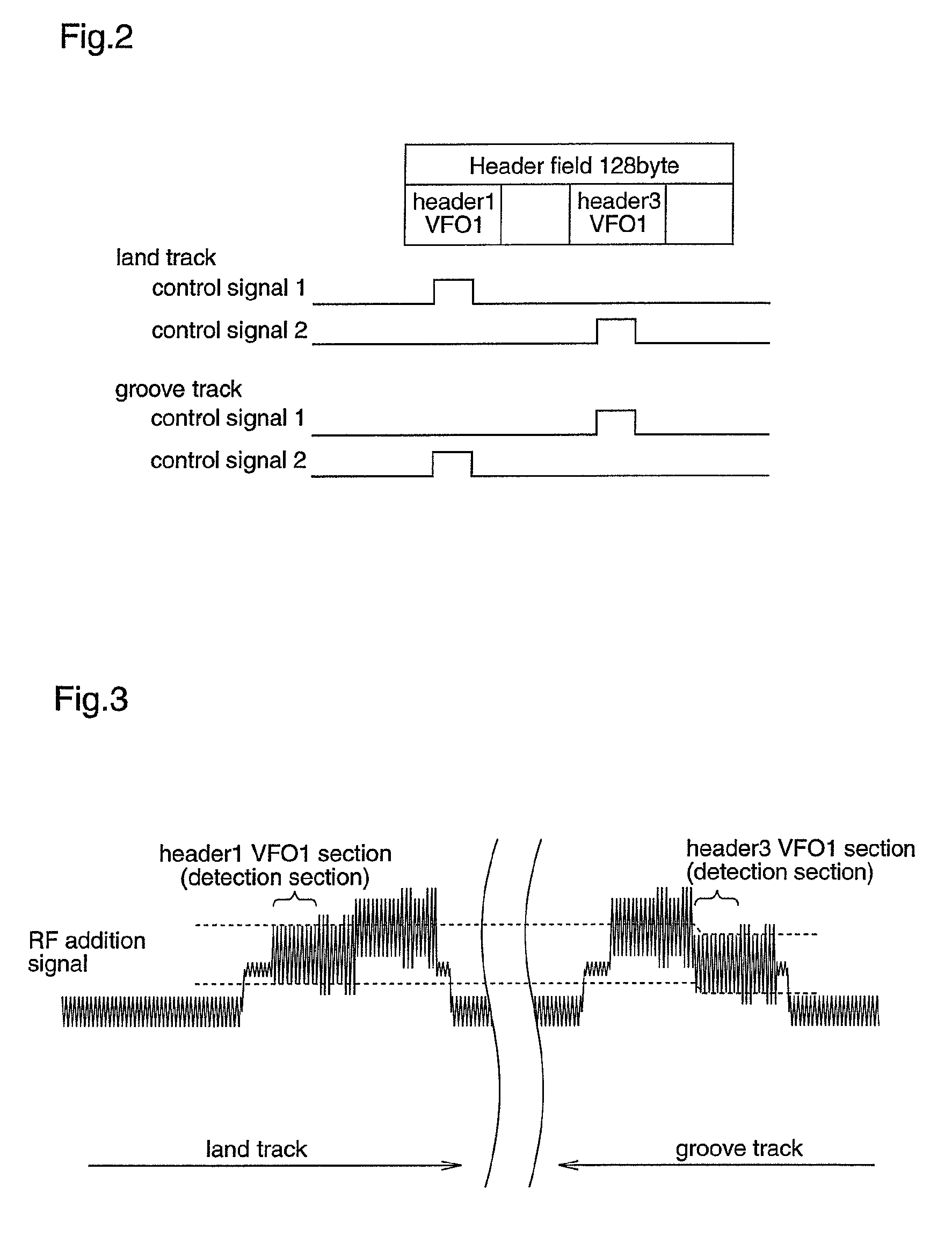
[0064]The optical disc recording / reproducing apparatus of the first embodiment records data in a land / groove recording type optical disc on which a land track and a groove track are alternately replaced with each other to form a single track from the inner circumference toward the outer circumference of the disc (e.g., DVD-RAM), and reproduces data from the optical disc. A header region formed of pits, which is called CAPA, is located at the beginning of each sector, and this pit sequence is arranged in an intermediate position between the land track and the groove track as shown in FIG. 11(a). FIG. 11(b) shows an RF signal obtained after the TE signals are added.

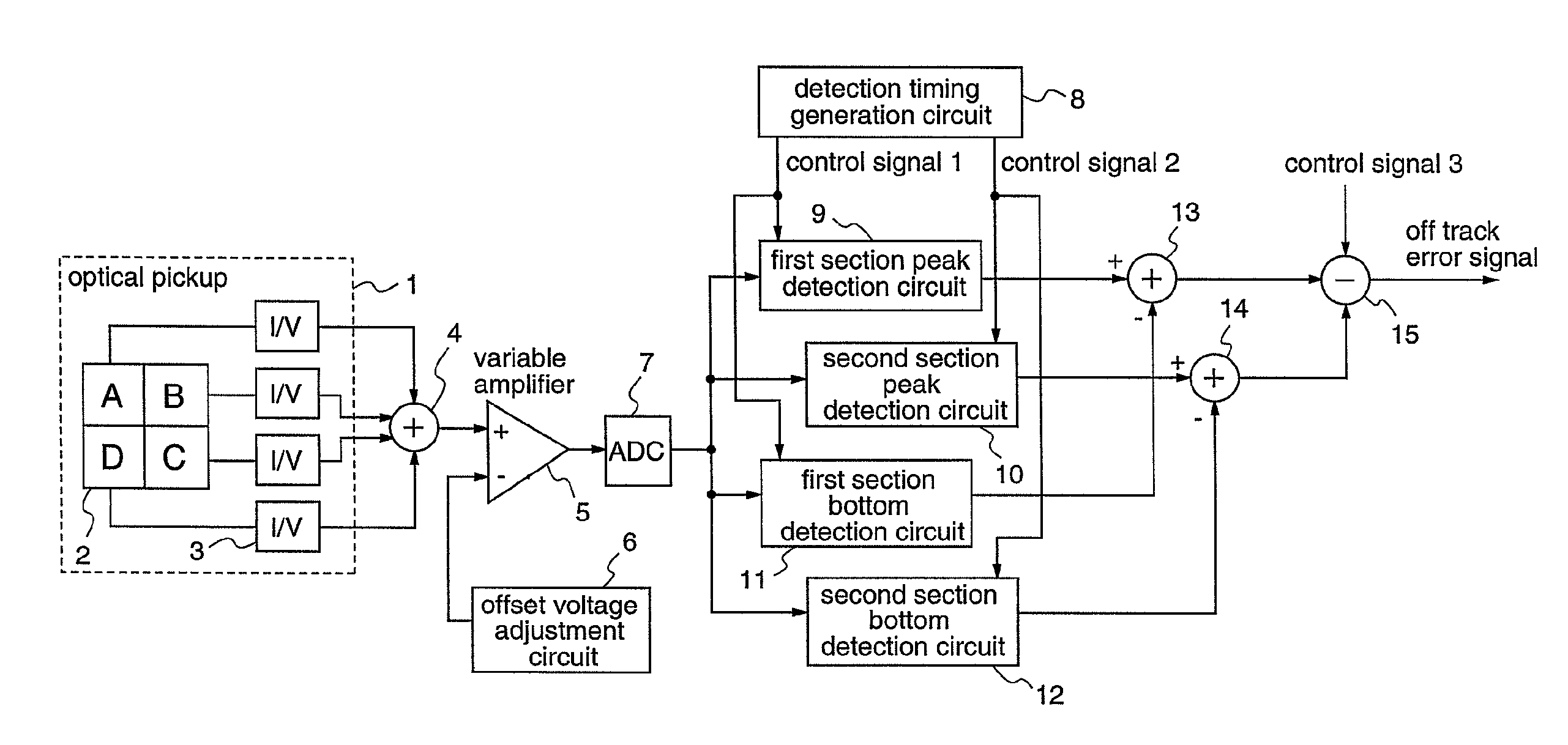
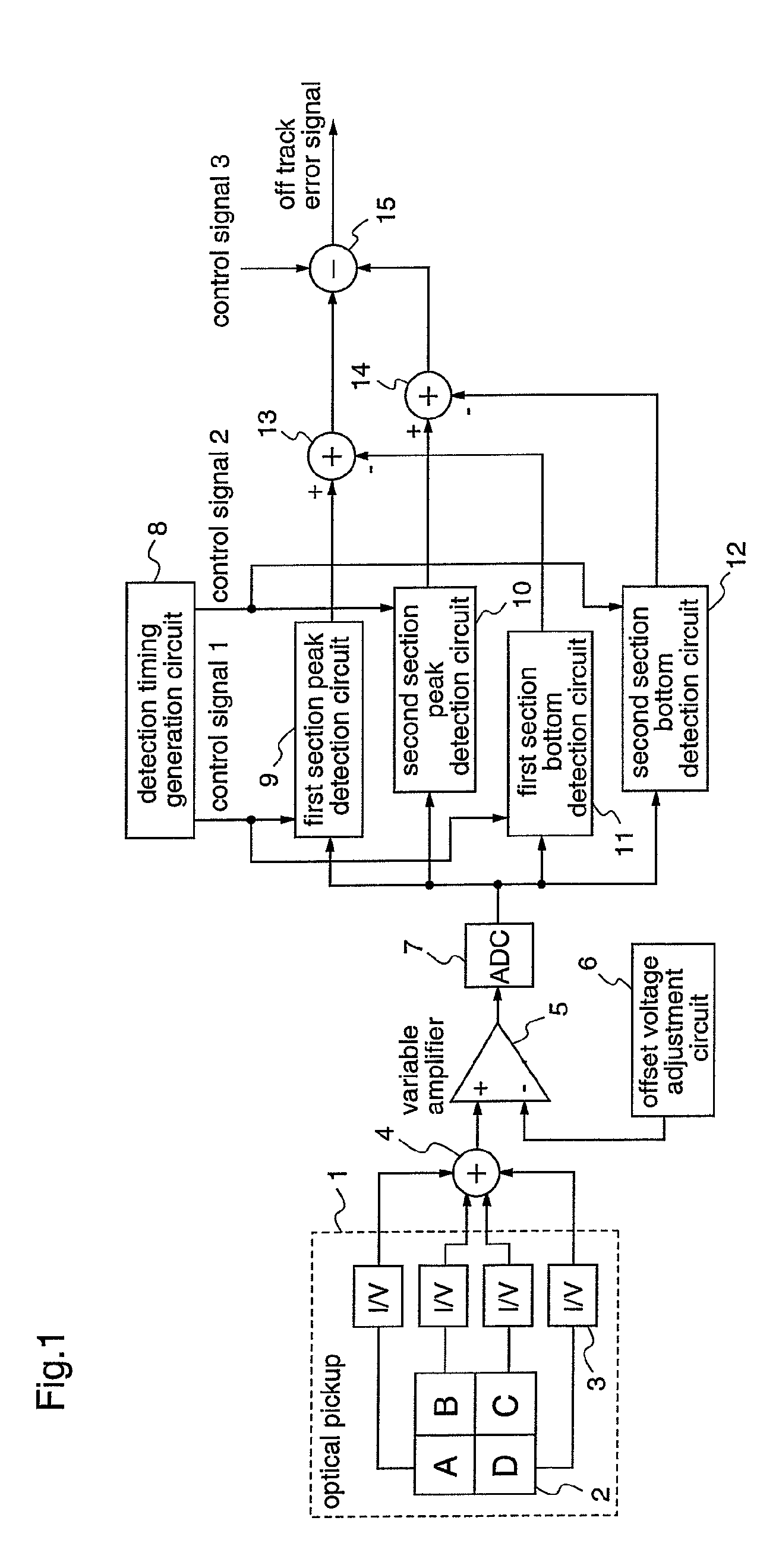
[0065]FIG. 1 is a block diagram illustrating the configuration of the optical disc recording / reproducing apparatus of the first embodiment.

[0066]The optical disc recording / reproducing...

embodiment 2

[0081]Hereinafter, an optical disc recording / reproducing apparatus according to a second embodiment of the present invention will be described.

[0082]The optical disc recording / reproducing apparatus of this second embodiment is different from the first embodiment in the control operations of the peak detection circuit and the bottom detection circuit.

[0083]FIG. 4 is a diagram for explaining the detection operation performed by the optical disc recording / reproducing apparatus of the second embodiment, wherein 4(a) shows a waveform obtained when updating a detected value, and 4(b) shows a waveform obtained when a held value in the detection circuit is updated as it is.

[0084]The peak detection circuits 9 and 10 and the bottom detection circuits 11 and 12 perform the detection operations in the detection operation sections, i.e., the VFO1 sections in the Header1 and Header3, and hold the just previously detected values in the sections other than the detection operation sections, as descr...

embodiment 3

[0095]Hereinafter, an optical disc recording / reproducing apparatus according to a third embodiment of the present invention will be described.

[0096]The optical disc recording / reproduction apparatus of the third embodiment is characterized in that the peak detection circuit and the bottom detection circuit are provided with follow-up functions in a droop response direction. The droop response direction is a direction along which the maximum value of the peak values and the minimum value of the bottom values which are held in the detection circuits are attenuated.

[0097]Hereinafter, the characteristics of the third embodiment will be described in comparison with the conventional detection circuit.

[0098]In the conventional detection circuit, the detection efficiency is determined by the ratio between the follow-up performance and the droop response performance, and the droop response performance must be decreased relative to the follow-up performance in order to maximize the detection a...


PUM

PropertyMeasurementUnit
polarityaaaaaaaaaa
densityaaaaaaaaaa
frequencyaaaaaaaaaa

Abstract

There is provided an optical disc recording / reproducing apparatus which can reduce the chip size using the high-miniaturization process and can enhance the detection accuracy. A signal which is obtained by amplitude-adjusting a header region in a reproduced signal detected by an optical pickup (1) is digitized, and peak detection or bottom detection from the reproduced signal in each of a first section and a second section in the header region is performed by detection circuits (9) to (12), respectively. Then, amplitude data in the first section and the second section are obtained by subtracters (13) and (14) from the detected values in the respective detection circuits. A difference in amplitude between the first section and the second section in the header region is obtained by a subtracter (15) based on the amplitude data, and the amplitude difference is outputted as an off-track error signal. The respective detection circuits (9) to (12) perform detection operations in the first and second sections, and hold the detection operations in the sections other than the first and second sections.

Description

TECHNICAL FIELD[0001]The present invention relates to extraction of a track center control signal for an optical disc recording / reproducing apparatus which records data in a disc on which tracks are formed, and reproduces data from the disc.BACKGROUND ART[0002]In recent years, price competition of optical disc recording / reproducing apparatuses has heated up, and the demand for cost reduction of electronic parts such as LSI have been extremely increased. Effective means to achieve such cost reduction include an increase in integration density by process miniaturization and a reduction in space by reducing analog circuits.[0003]Generally, a guide groove for guiding a beam spot of a light beam during data recording is formed on a recordable optical disc, and data are recorded along this guide groove. The guide groove is wobbled with a specific frequency to generate a reference clock for controlling the number of rotations of the disc. There is a land / groove recording system DVD-RAM in ...

Claims


Application Information

Patent Timeline
Patent Type & Authority Patents(United States)
IPC IPC(8): G11B7/00
CPCG11B7/00745G11B7/0053G11B7/00718
Inventor ICHIRYU, DAISAKAI, MITSURU
Owner PANASONIC SEMICON SOLUTIONS CO LTD
Why Eureka
Try Eureka