MIG welding pliers

a technology of mig welding pliers and pliers, which is applied in the field of pliers, can solve the problems of reducing the overall affecting the quality of the weld, and reducing the welding performance, so as to improve the productivity of the welder, improve the removal speed and easy removal of spatter

Inactive Publication Date: 2011-08-23
CARTER RAHMAN
View PDF11 Cites 9 Cited by
  • Summary
  • Abstract
  • Description
  • Claims
  • Application Information

AI Technical Summary

Benefits of technology

[0003]Embodiments of the present invention provide an improvement to MIG welding pliers which allow faster and easier removal of spatter form a MIG welding nozzle, thereby improving welder productivity. Prior art MIG welding pliers (for example, the WELPER YS-50, distributed by RADNOR WELDING PRODUCTS, of Radnor Pa., USA) provide a flat, smooth, outer surface on the pinchers of the pliers. Embodiments of the present invention provide a rounded file on the outer surface of each of the pinchers of the pliers. In one embodiment, each pincher has a different file surface. For example, one pincher may have a double cut, coarse file on its outer surface, and the other pincher may have a single cut, smooth file on its outer surface. The rounded file surface provides for improved spatter removal, and increases the efficiency of MIG welders, as they spend less time removing spatter from their nozzles since a single tool performs both pliers functions, cutting functions, and filing functions. Time is saved since the welder does not have to change to a different hand tool to perform a filing operation for spatter removal.

Problems solved by technology

During use, small particles of molten metal, known as “spatter” adhere to the nozzle, which degrades welding performance, and can adversely affect the quality of the welds.
This time-consuming activity reduces the overall productivity of the welder.

Method used


Image

  • MIG welding pliers
  • MIG welding pliers
  • MIG welding pliers

Examples


Embodiment Construction

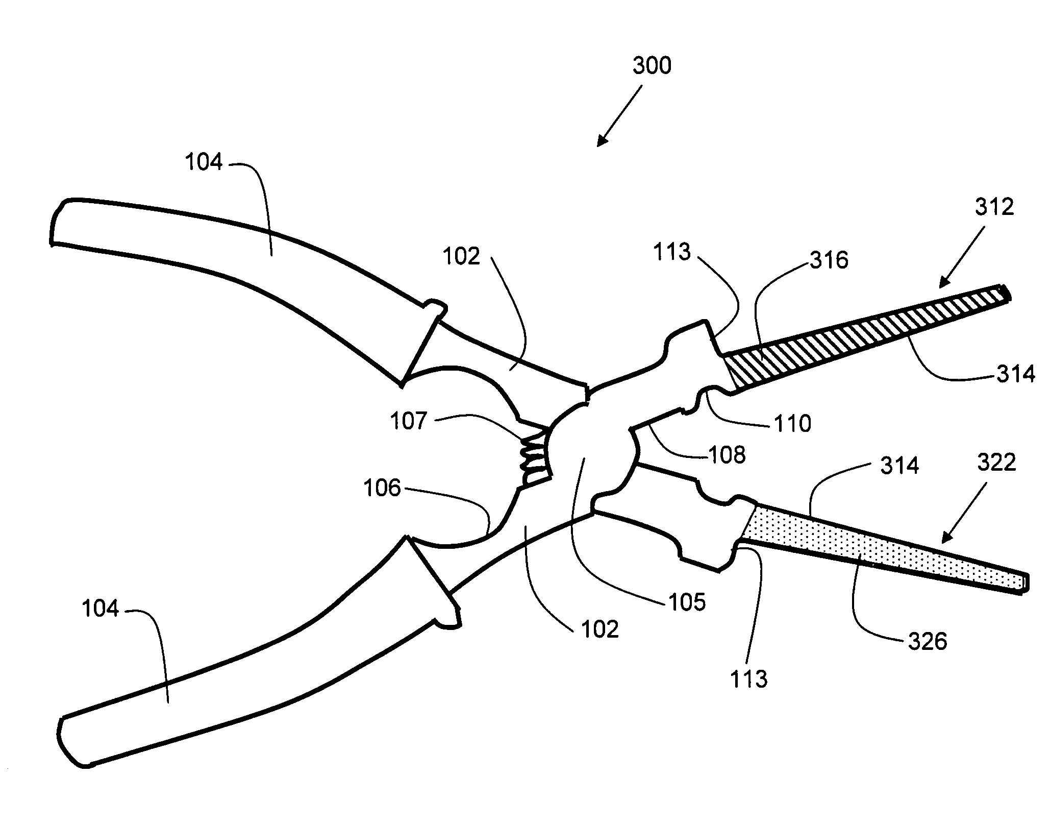
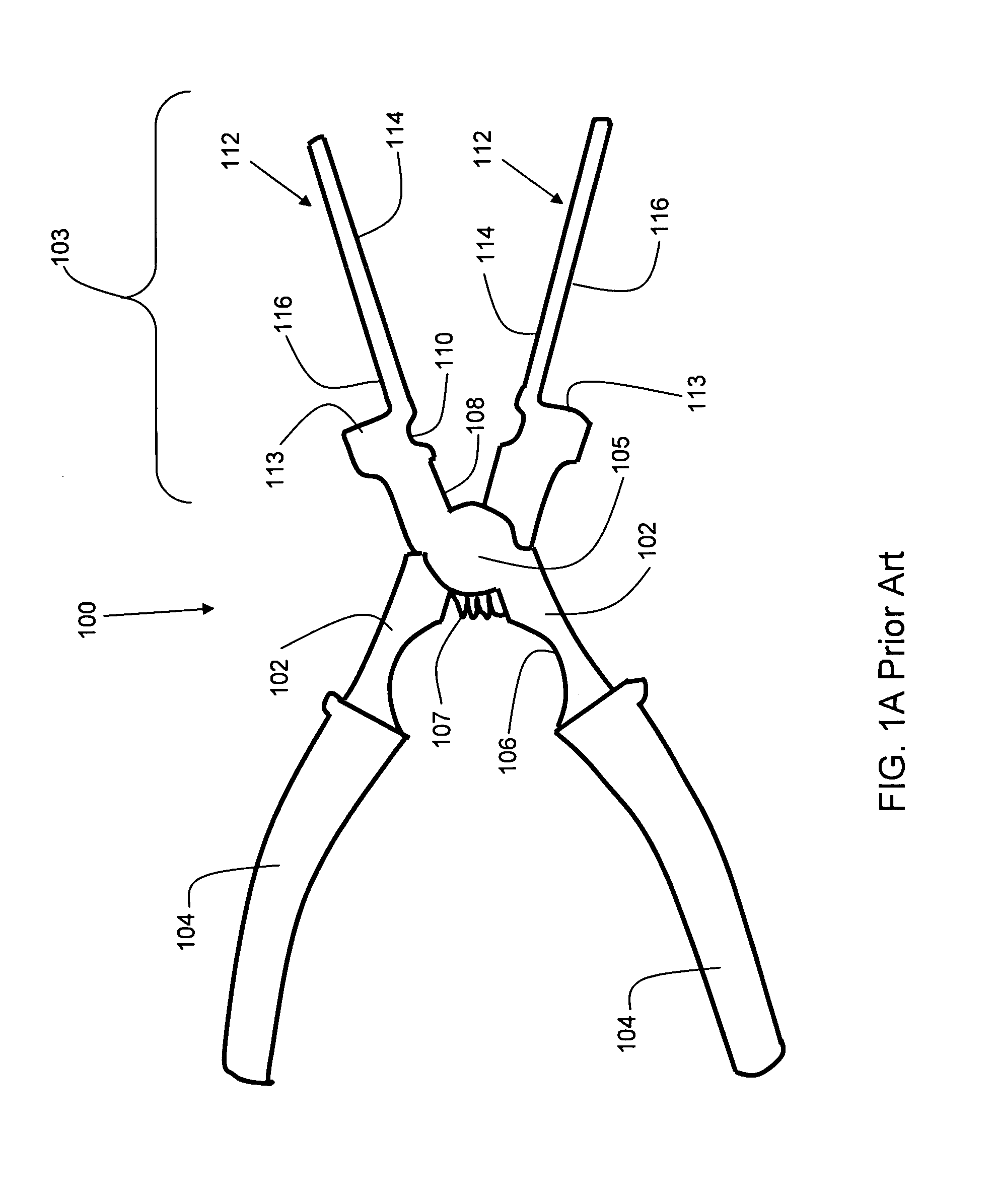
[0035]For the purpose of providing context, the prior art will be briefly discussed. FIG. 1A shows a prior art MIG pliers 100. Pliers 100 comprises two handles 102, each having a gripping surface 104. The handles 102 are joined at pivot point 105 as is known in the art, and is often formed by a rivet (not shown). A spring 107 is disposed between the two handles 102 to provide convenient opening and closing of the pliers. Each handle 102 has a large interior curved portion 106, which is useful for nozzle removal and installation. The portion of the pliers to the right of pivot 102 in FIG. 1 is referred to generally as the head section 103.

[0036]Head section 103 comprises two jaws 112. Each jaw 112 comprises a cutting surface 108, which is useful for wire cutting, a small interior curved portion 110, suited for removing and installing contact tips. Anvil portion 113 is smooth, and is used for removing spatter from the nozzle end. Each jaw 112 has an inner surface 114 and an outer surf...


PUM


Abstract

An improved MIG welding pliers is disclosed, which allows faster and easier removal of spatter form a MIG welding nozzle, thereby improving welder productivity. Embodiments of the present invention provide a rounded file on the outer surface of each of the pinchers of the pliers. In one embodiment, each pincher has a different file surface. The rounded file surface provides for improved spatter removal, and eliminates the need for waxes and spatter control products which degrade the contact tip and nozzle, hastening the need for their replacement. Therefore, embodiments of the present invention increase the efficiency of a MIG welding operation, as less time is spent removing spatter from nozzles, and thus, more time is available for welding. Furthermore, by avoiding the use of waxes, costs are reduced since nozzles and contact tips do not need to be replaced as frequently.

Description

FIELD OF THE INVENTION[0001]The present invention relates generally to hand tools, and more specifically to pliers.BACKGROUND[0002]MIG (Metal Inert Gas) Welding is an arc welding process in which a continuous and consumable wire electrode and shielding gas are fed through a welding gun. During use, small particles of molten metal, known as “spatter” adhere to the nozzle, which degrades welding performance, and can adversely affect the quality of the welds. Periodically, the welder must stop welding, and clean the nozzle. This time-consuming activity reduces the overall productivity of the welder. It is therefore desirable to have an improved tool for MIG welding to address the aforementioned problems.SUMMARY OF THE INVENTION[0003]Embodiments of the present invention provide an improvement to MIG welding pliers which allow faster and easier removal of spatter form a MIG welding nozzle, thereby improving welder productivity. Prior art MIG welding pliers (for example, the WELPER YS-50,...

Claims


Application Information

Patent Timeline
Patent Type & Authority Patents(United States)
IPC IPC(8): B25B7/22
CPCB25B7/02B25B7/22
Inventor CARTER, RAHMAN
Owner CARTER RAHMAN
Why Eureka
Try Eureka