Combination of screw with stabilized strength and screwdriver bit, and header punch for manufacturing the screw with stabilized strength

a technology of stabilized strength and screwdriver bit, which is applied in the direction of screwdrivers, wrenches, fastening means, etc., can solve the problems of high manufacturing cost, low strength, and considerable effort required in screw manufacturing, and achieve high working efficiency, stable screw in terms of strength, and engagement operation

Inactive Publication Date: 2011-08-23
TOTSU
View PDF32 Cites 4 Cited by
  • Summary
  • Abstract
  • Description
  • Claims
  • Application Information

AI Technical Summary

Benefits of technology

[0103]In the screw with stabilized strength of the present invention, as a result of the modification of the shape and structure of the bit engaging groove in a screw in which a Y-shaped bit engaging groove is formed in the screw head, the engagement operation with the corresponding screwdriver bit is easy, the occurrence of the phenomenon of “come-out” is prevented so that the working efficiency is high, and a uniform dispersion of torque transmission is realized so that this transmission is smooth and sufficient, thus stabilizing the screw in terms of strength as well.
[0104]In the screw with stabilized strength of the present invention, as a result of the shape and structure of the bit engaging groove, the strength of the header punch that is used to manufacture this screw is high, and as a result, the mass production of a screw of this type is made possible. Furthermore, since the engaging operation with the screwdriver bit is easy, application to recycled products and maintenance work is facilitated or made more efficient, so that the screw is usable advantageously as an all-purpose screw. In particular, in the screw with stabilized strength of the present invention, since inclined surface portions are formed in the boundary portions which are between the respective branching grooves of the bit engaging groove in the screw head, an appropriate engaging operation of the tip end blade part of the screwdriver bit with respect to the bit engaging groove can be advantageously accomplished smoothly and quickly.
[0105]In the combination of a screw with stabilized strength and a screwdriver bit of the present invention, as a result of the shape and structure of the bit tip end being modified in accordance with the shape and structure of the bit engaging groove of the above-described screw with stabilized strength, a connection with the screw with stabilized strength is accomplished quickly and easily. Furthermore, the phenomenon of “come-out” during screw tightening work is securely prevented, and the working characteristics are improved. Moreover, other effects such as the stabilization of the strength of the bit tip end blade part so that a structure that is superior in terms of safety can be formed and the like are also obtained. More specifically, in the combination of a screw with stabilized strength and a screwdriver bit of the present invention, since the tip end blade part of the screwdriver bit is reinforced, damage and displacement of the tip end blade part during tightening of the screw is eliminated, so that problems such as various types of trouble with the screw, “come-out” and the like is completely prevented, and the combination is advantageously utilized as an all-purpose tightening fitting.
[0106]In the combination of a screw with stabilized strength and a screwdriver bit of the present invention, as a result of the shape and structure of the bit engaging groove, the structure of the tip end blade part of the corresponding screwdriver bit is reinforced. Consequently, damage and displacement (bending and the like) of the tip end blade part during screw tightening work is eliminated, so that problems such as various types of trouble with the screw, “come-out” and the like is completely prevented, and a screw that is superior in terms of wear resistance is obtained. Accordingly, the advantage of maintenance-free operation when the present invention is applied to automated machinery is obtained, and the combination is advantageously utilized as an all-purpose tightening fitting.
[0107]In the header punch of the present invention used for the manufacture of the screw with, stabilized strength, as a result of the modification of the shape and structure adapted to form the bit engaging groove of the screw with stabilized strength, a screw with stabilized strength which is stabilized in terms of strength as described above is manufactured easily and at a low cost. More specifically, as a result of the shape and structure of the punch being modified in accordance with the shape and structure of the bit engaging groove of the screw with stabilized strength, the strength of the punch is stabilized so that the durability is improved, which is extremely effective for the mass production of screws of this type.

Problems solved by technology

As a result, they have such problems that considerable effort is required in the manufacture of the screw and screwdriver, and the manufacturing cost is high.
As a result, in regard to the shape of the tip end blade part of the corresponding screwdriver bit as well, the thickness of the blade pieces that engage with the respective branching groves is small, thus resulting in a drop in strength, so that there are difficulties in terms of durability.
In this case, however, there are difficulties.
Accordingly, conventional combinations of screws and screwdrivers of this type are limited to special applications.
In this case, however, the shape of the bit engaging groove of the screw and the shape of the tip end blade pars of the screwdriver bit respectively become more complicated, leading to complications in manufacture and an increase in the manufacturing cost.

Method used


Image

  • Combination of screw with stabilized strength and screwdriver bit, and header punch for manufacturing the screw with stabilized strength
  • Combination of screw with stabilized strength and screwdriver bit, and header punch for manufacturing the screw with stabilized strength
  • Combination of screw with stabilized strength and screwdriver bit, and header punch for manufacturing the screw with stabilized strength

Examples


embodiment 1

Example of Construction 1 of Screw with Stabilized Strength

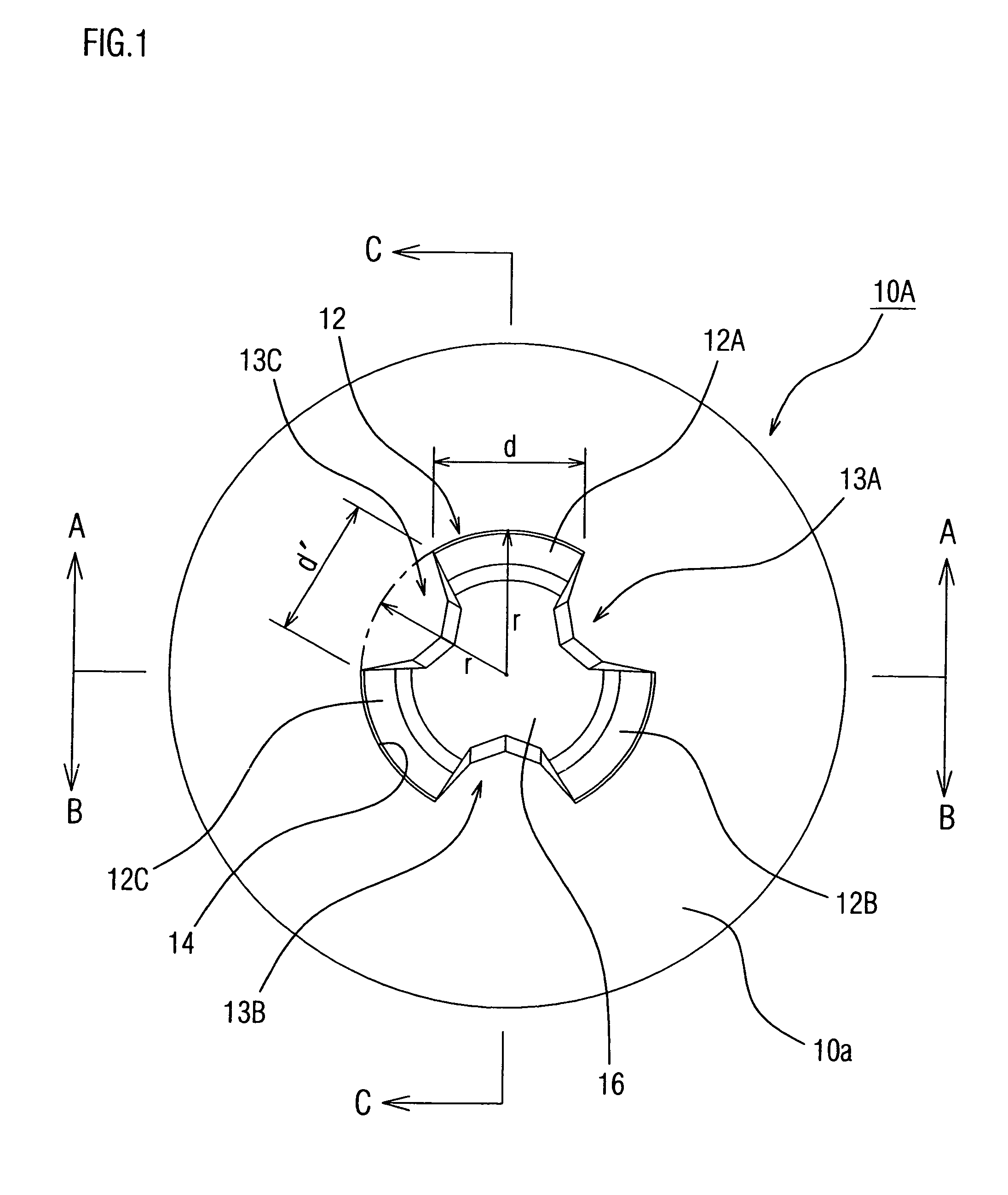
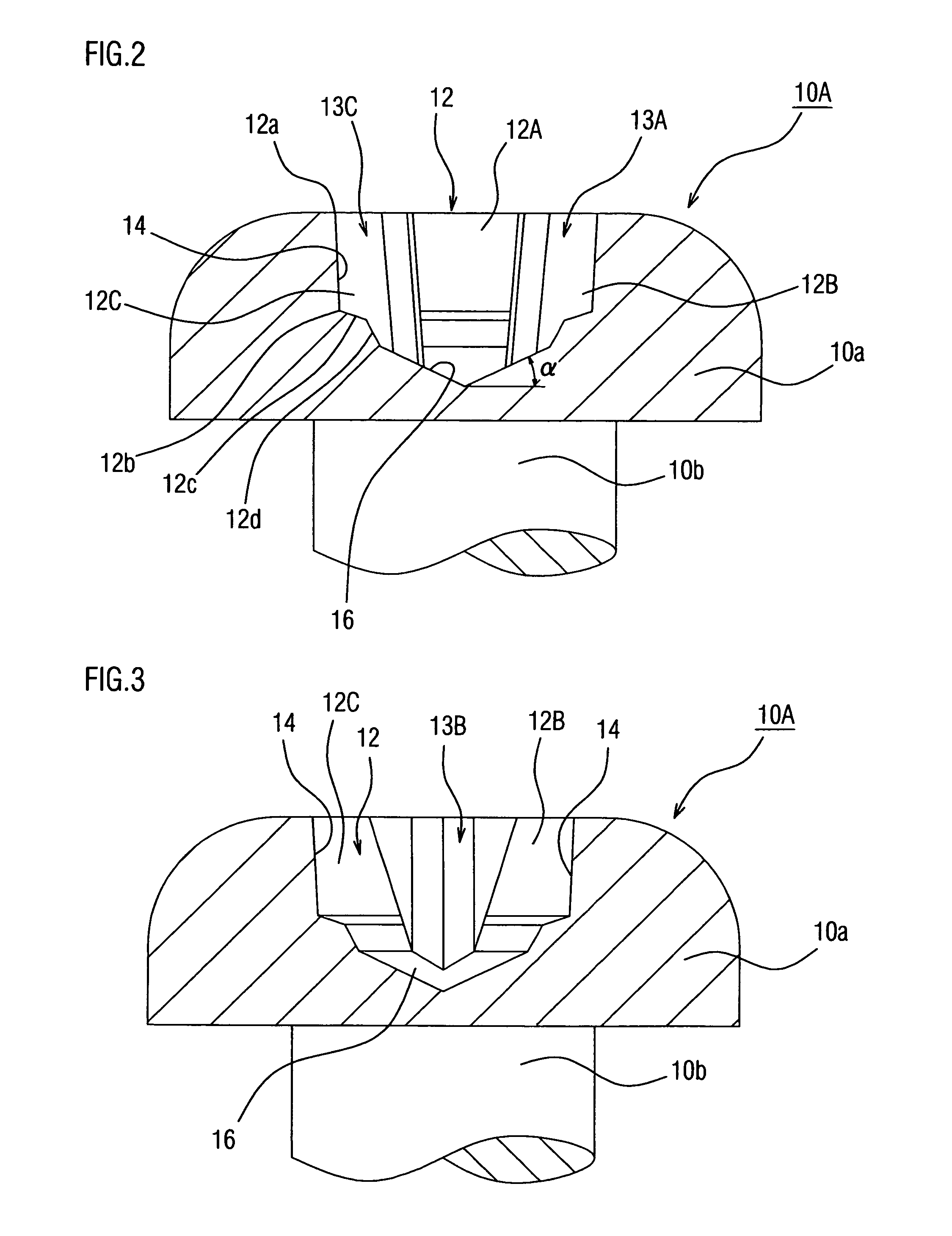
[0187]FIGS. 1 through 4 show a first embodiment of the screw with stabilized strength according to the present invention. More specifically, in FIGS. 1 through 4, the reference numeral 10A indicates the screw with stabilized strength according to the present invention. The head 10a of this screw 10A is formed in the shape of a pan, and a bit engaging groove 12 is formed in the center of the top part of this head 10a.

[0188]The bit engaging groove 12 of the screw with stabilized strength 10A in the present embodiment has a construction in which the groove 12 is divided into three substantially equal parts in the circumferential direction to form a Y shape at a specified radial distance r from the central portion of the screw head 10a. In this case, the groove width d of the respective branching bit engaging grooves 12A, 12B and 12C extending in the direction of the radius r from the central portion of the bit engaging groove ...

embodiment 2

Example of Construction 2 of Screw with Stabilized Strength

[0192]FIGS. 5 through 8 show another embodiment of the screw with stabilized strength according to the present invention. More specifically, in FIGS. 5 through 8, the reference numeral 10B indicates the screw with stabilized strength of this embodiment. The head 10a of this screw 10B is formed in the shape of a pan, and a bit engaging groove 12 is formed in the center of the top part of the head 10a.

[0193]The bit engaging groove 12 of the screw with stabilized strength 10B in the present embodiment is basically the same as the bit engaging groove 12 of the screw with stabilized strength 10A described in the above-described Embodiment 1. Accordingly, portions of the construction that are the same as the construction described in the above-described FIGS. 1 through 4 are labeled with the same reference numerals, and a detailed description of such portions is omitted. However, the bit engaging groove 12 of the screw with stabi...

embodiment 3

Example of Construction 3 of Screw with Stabilized Strength

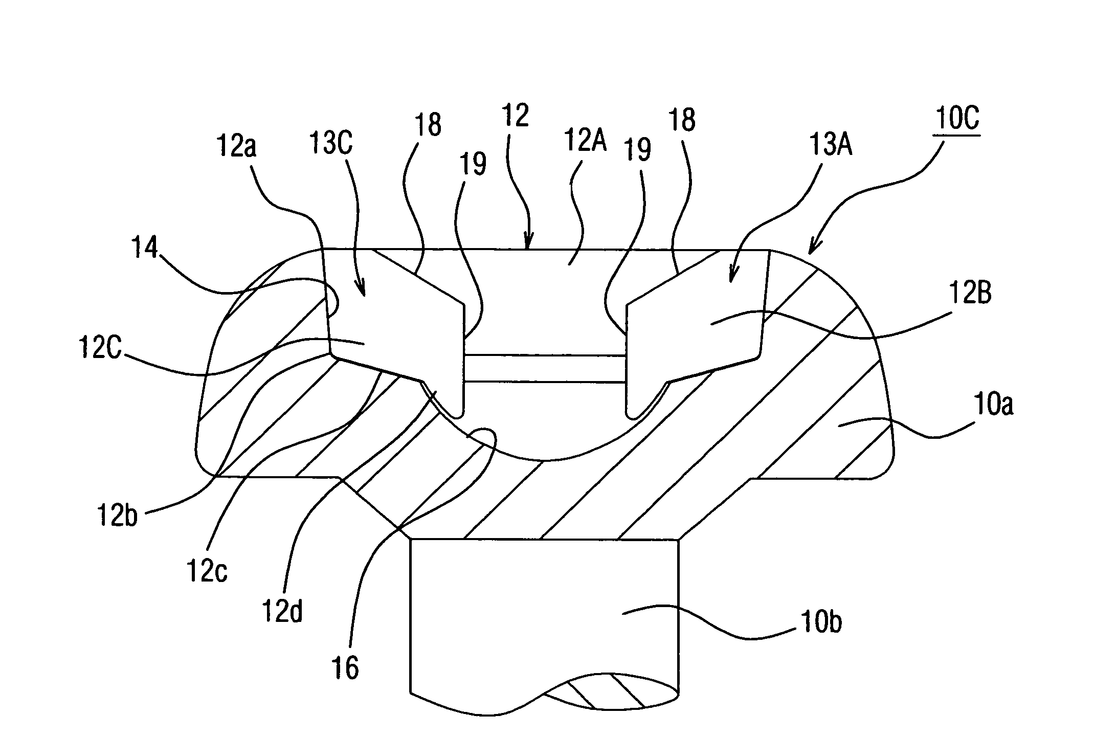
[0197]FIGS. 9 through 12 show a third embodiment of the screw with stabilized strength of the present invention. More specifically, in FIGS. 9 through 12, the reference numeral 10C indicates the screw with stabilized strength of the present embodiment; and the head 10a of this screw 10C is formed in the shape of a pan, and a bit engaging groove 12 is formed in the center of the top part of this head.

[0198]The bit engaging groove 12 of the screw with stabilized strength 10C in the present embodiment has a construction which is formed in a Y shape divided into three substantially equal parts in the circumferential direction at a specified radial distance r from the central portion of the screw head 10a. In this case, the groove width d of the respective branching grooves 12A, 12B and 12C extending in the direction of the radius r from the central portion of the bit engaging groove 12 is formed so that this width gradually expa...


PUM


Abstract

A screw having stabilized strength, combination with a driver bit that best fits the screw, and a header punch for producing the screw. The screw having stabilized strength has letter Y-shaped bit-fitting grooves formed in the head portion of the screw. Forming the grooves makes fitting of a corresponding driver to the screw easy, prevents occurrence of a cam-out phenomenon to enhance work efficiency, makes torque transmission to be made smoothly and sufficiently, and stabilizes strength. The bit-fitting grooves are formed in a letter Y shape that is substantially equally divided into three sections in the circumferential direction, the grooves being formed at positions required distances away from the central portion of the screw head. The width of each of the grooves extending in radial directions from the central portion of the bit-fitting grooves is set so that the grooves are gradually expanded and substantially equally spaced with spacing each equal to the width of a boundary section between adjacent grooves. Further, the outer peripheral end wall surface of each bit-fitting groove is made substantially vertical from an opening edge section up to a required depth. The outer peripheral end wall surface is displaced downward from a lower edge section of the wall surface toward the central portion of the screw head, and the center where the wall surfaces meet are formed as a substantially conical bottom surface.

Description

TECHNICAL FIELD[0001]The present invention relates to a combination of a screw, in which a bit engaging groove formed in the screw head is divided into three equal parts in the circumferential direction so that a three-way groove respectively extending in the form of a letter “Y” in the radial direction from the central portion is formed, and a screwdriver bit, which has three tip end vane parts corresponding to the three-way groove and is suitable for use with this screw, and further relates to a header punch used to manufacture the such a screw.BACKGROUND ART[0002]Conventionally, in cases where screws are unnecessarily removed by a third party from devices that are completed by the connection or assembly of various types of parts by means of screw attachment, disassembly of the device or the separation of parts is performed, and adjustment locations or dangerous locations are exposed, so that it is difficult to restore the function of the device to its original form, and so that p...

Claims


Application Information

Patent Timeline
Patent Type & Authority Patents(United States)
IPC IPC(8): B25B23/00F16B35/06B21K1/46B25B15/00F16B23/00
CPCB21K1/463F16B23/0007B25B15/005F16B23/00B25B15/00
Inventor TOTSU, KATSUYUKI
Owner TOTSU
Why Eureka
Try Eureka