
Device for measuring thermal properties in a medium and method for determining the moisture content in the medium

a technology of thermal properties and devices, applied in the direction of automatic control, process and machine control, instruments, etc., can solve the problems of not being able to apply for determining ground humidity, unable to achieve direct, gas-permeable connection, and unable to achieve the effect of determining ground humidity, and achieving low set-up costs, simple assembly and operation

Inactive Publication Date: 2011-08-23
PLANTCARE
View PDF10 Cites 7 Cited by
  • Summary
  • Abstract
  • Description
  • Claims
  • Application Information

AI Technical Summary

Benefits of technology

"The invention is a device and method for measuring humidity in media using a thermal measurement method. The device is designed to be reliable and sensitive with respect to the water content of the surrounding medium, and can be manufactured in an inexpensive manner. The measurement is based on the heating and cooling of the measurement tip, which is designed to minimize energy consumption and has a high sensitivity with respect to humidity fluctuations. The device can be easily inserted into soil or other substrates, and the measurement tip is protected from corrosion. The invention provides a solution for the measurement of humidity in media that is reliable, sensitive, and cost-effective."

Problems solved by technology

Whilst the measurement of the relative air humidity today is possible in a very simple manner by way of conventional as well as electronic sensors, the measurement of the humidity in mixtures however, in particular of ground or plant substrates, is still problematic.
This principle is very suitable for measuring air humidity, but may not however be applied for determining the ground humidity.
A direct, gas-permeable connection however creates enormous difficulties.
The filter also becomes infested with ground bacteria and ions may migrate through the filter into the sensor region, and destroy it.
Furthermore, the sensor including the activation and evaluation electronics is expensive and thus not suitable for large-scale application.
Apart from further disadvantages, all these methods entail high costs and also, to some extent, a considerable technical effort.
The porous measurements bodies need to be in direct connect with the surrounding substrate over the whole surface, and thus may easily become blocked or also calcified for example with calciferous water.
Furthermore, the manufacturing costs of such a sensor are relatively high and lie in the region of 30-50 Euros.
A direct electronic evaluation entails a considerable expense, since for this, the sagging of the membrane needs to be converted into an electronic signal.
This method however has not asserted itself up to now, despite various developments.
This sensor too is unreliable since the border surface between the heating element and the soil, as well as between the temperature probe and the soil, is not defined.
This method has the disadvantage that the difference between the start and end temperature depends on the water content only to a limited extent, i.e. the sensitivity of such a method is very poor.
Furthermore, on measuring, the thermal conductivity of the soil through the thin material dominates, so that the measurement becomes unreliable on account of an undefined (thermal) composition of the surrounding soil.
Furthermore, soil is often compressible and evades pressure.
The disadvantage of this method lies in the fact that the ceramics are not enriched with water to an equal extent as the surrounding soil, since the distribution of water-suctioning pores between the soil and the ceramic is very different.
The sensitivity is poor since only a fraction of the volume of the ceramics is present in the form of pores.
For the above mentioned reasons, and in particular on account of the high costs, none of the methods which are based on the thermal measurement principle have asserted themselves until now.

Method used


Image

  • Device for measuring thermal properties in a medium and method for determining the moisture content in the medium
  • Device for measuring thermal properties in a medium and method for determining the moisture content in the medium
  • Device for measuring thermal properties in a medium and method for determining the moisture content in the medium

Examples


Embodiment Construction

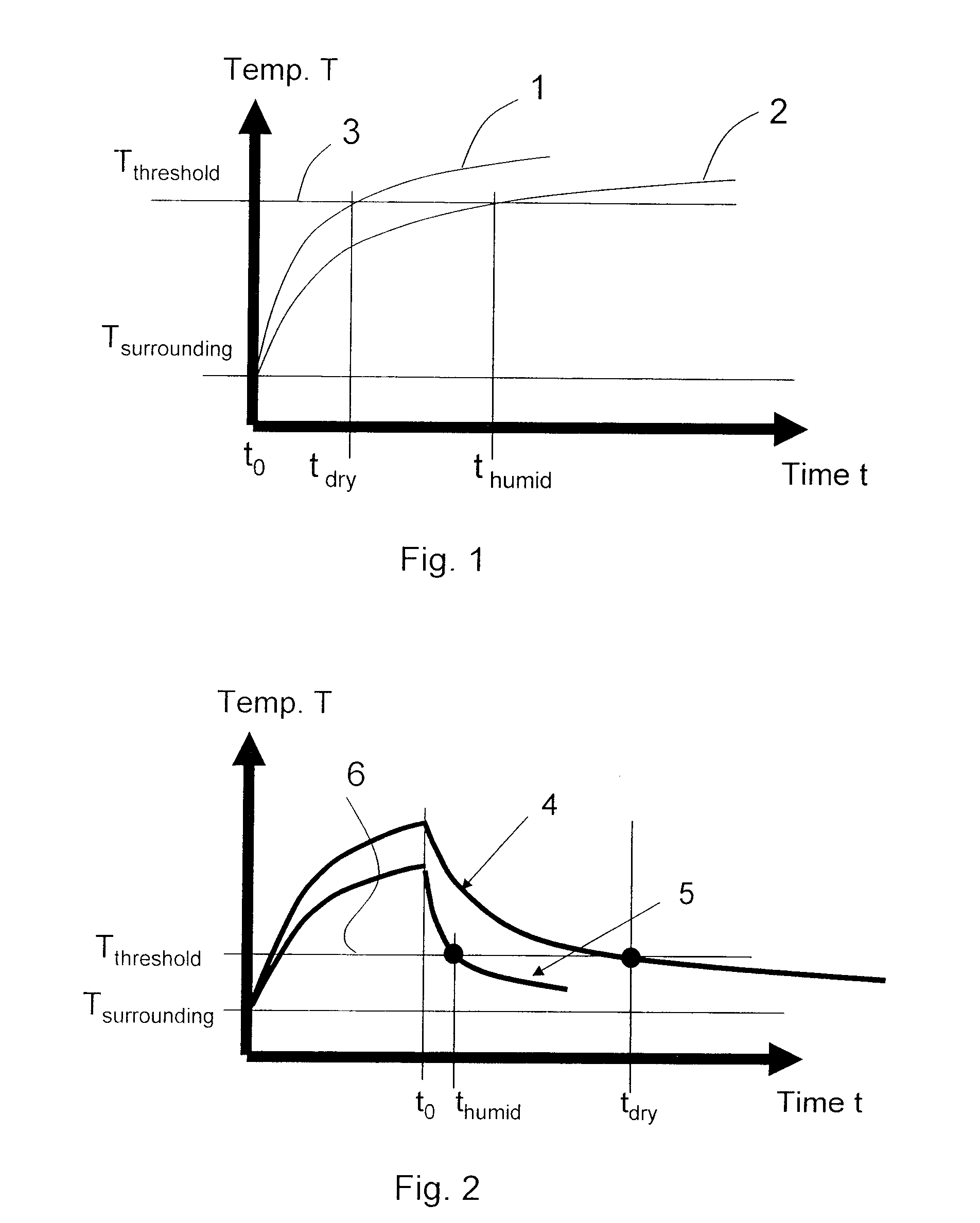
[0084]FIG. 1 shows a typical curve course of the temperature on evaluating a heat-up phase with a high and low humidity in a ground sample. A curve 1 shows the temperature course for a substrate with a low moisture content, a further curve 2, the temperature course for a humid substrate. Thus two times, tdry or thumid, corresponding to the crossing points of the threshold value with the two curves 1, 2, may be allocated to a temperature threshold value 3, and an action may be triggered on falling below a critical time.

[0085]FIG. 2 shows a typically curve course of the temperature with the evaluation of a cooling phase, with a high and low humidity in a ground sample. A curve 4 in turn shows the temperature curve for a substrate with a low moisture content, and a further curve 5 shows the temperature course for a humid substrate. Again two times, tdry and thumid given by the crossing points of the threshold value with the declining branch of the two curves are allocated to a given te...


PUM

PropertyMeasurementUnit
thicknessaaaaaaaaaa
thicknessesaaaaaaaaaa
timeaaaaaaaaaa

Abstract

The invention relates to a method and device for determining the water content of a medium, particularly of soils and the like, in which a probe or sensor (8) located in the medium is heated. A temporary change in temperature is effected by dissipating the thermal energy through the moisture in the area surrounding the probe, this change in temperature being used for determining the moisture content of the medium. An intermediate layer (13) is placed between the probe and the surrounding medium and is absorbent and mechanically deformable for mechanically coupling the probe to the surrounding medium and for decoupling the probe and the surrounding medium thereby enabling a precise measurement of moisture content to ensue while being subjected to the least possible thermal influence by the largely undetermined surrounding medium.

Description

BACKGROUND OF THE INVENTION[0001]1. Field of the Invention[0002]The invention relates to a device for determining thermal properties of a medium, in particular humidity sensors, and to a method for the measurement of humidity in a medium, in particular of soil.[0003]2. Description of Related Art[0004]Whilst the measurement of the relative air humidity today is possible in a very simple manner by way of conventional as well as electronic sensors, the measurement of the humidity in mixtures however, in particular of ground or plant substrates, is still problematic.[0005]Electronically functioning humidity sensors mostly operate on the basis of dielectric layers absorbing moisture, which have a dielectric constant which is greatly dependent on the water content. These layers are introduced between two electrode layers which form a plate capacitor and which measure the change of capacitance of this capacitor by way of an applied alternating voltage.[0006]This principle is very suitable ...

Claims


Application Information

Patent Timeline
Patent Type & Authority Patents(United States)
IPC IPC(8): G01N25/64
CPCA01G25/167G01N25/56G01N33/246Y10T137/189
Inventor SCHMIDT, WALTER
Owner PLANTCARE
Learn More