Controlled copper leach recovery circuit

a recovery circuit and copper leach technology, applied in the field of controlled copper leach recovery circuits, can solve the problems of large concentrations of soluble metal and metal precipitate lost in metal-depleted, low overall process yield, and high cost of secondary metal recovery, and achieve the effect of efficient secondary metal recovery and low grade extraction circuits that remain substantially constan

Active Publication Date: 2011-08-23
FREEPORT MCMORAN COPPER & GOLD INC
View PDF30 Cites 14 Cited by
  • Summary
  • Abstract
  • Description
  • Claims
  • Application Information

AI Technical Summary

Benefits of technology

[0008]For example, in accordance with the various exemplary embodiments of the present invention, the present process comprises (a) providing a HGPLS to a solution extractor unit within a single solution extraction plant, (b) producing a high grade raffinate and a metal-loaded organic solution by contacting the HGPLS with a partially loaded organic solution in the solution extractor, (c) providing a LGPLS to a different solution extractor unit within the same solution extraction plant, and (d) producing a low grade raffinate and the partially loaded organic solution by contacting the LGPLS with a barren organic flow containing a metal-specific extraction reagent. Furthermore, in accordance with the various embodiments of the present invention, the flow rate and reagent concentration of the barren organic flow containing a metal-specific extraction reagent can be altered based on the incoming metal material quality to maintain a constant concentration of metal in the low grade raffinate, allowing for efficient secondary metal recovery, including but not limited to cobalt recovery. In accordance with an exemplary embodiment of the present invention, the concentration of metal in the LGPLS may be adjusted by blending a portion of the LGPLS with the high grade pregnant leach solution so that the quantity of metal entering the low grade extraction circuit remains substantially constant.

Problems solved by technology

However, under these current leaching and solution extraction processes, large concentrations of soluble metal and metal precipitate can be lost in the metal-depleted, acid-containing aqueous phase raffinate solutions.
These losses lead to inefficiencies and low overall process yields.
Additionally, these high metal concentrations in the raffinate make recovery of secondary metals costly and possibly impractical.

Method used


Image

  • Controlled copper leach recovery circuit
  • Controlled copper leach recovery circuit
  • Controlled copper leach recovery circuit

Examples


Embodiment Construction

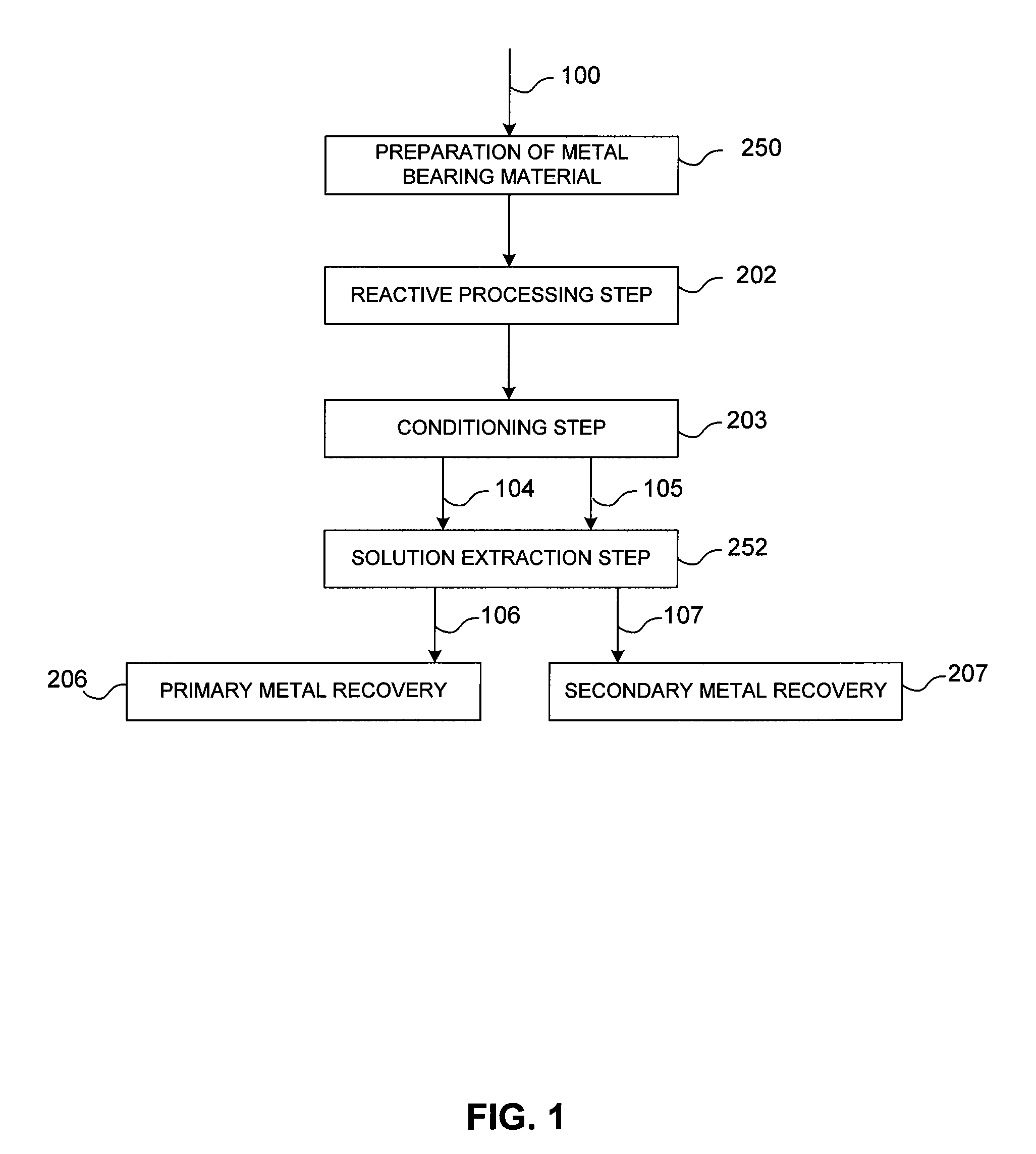
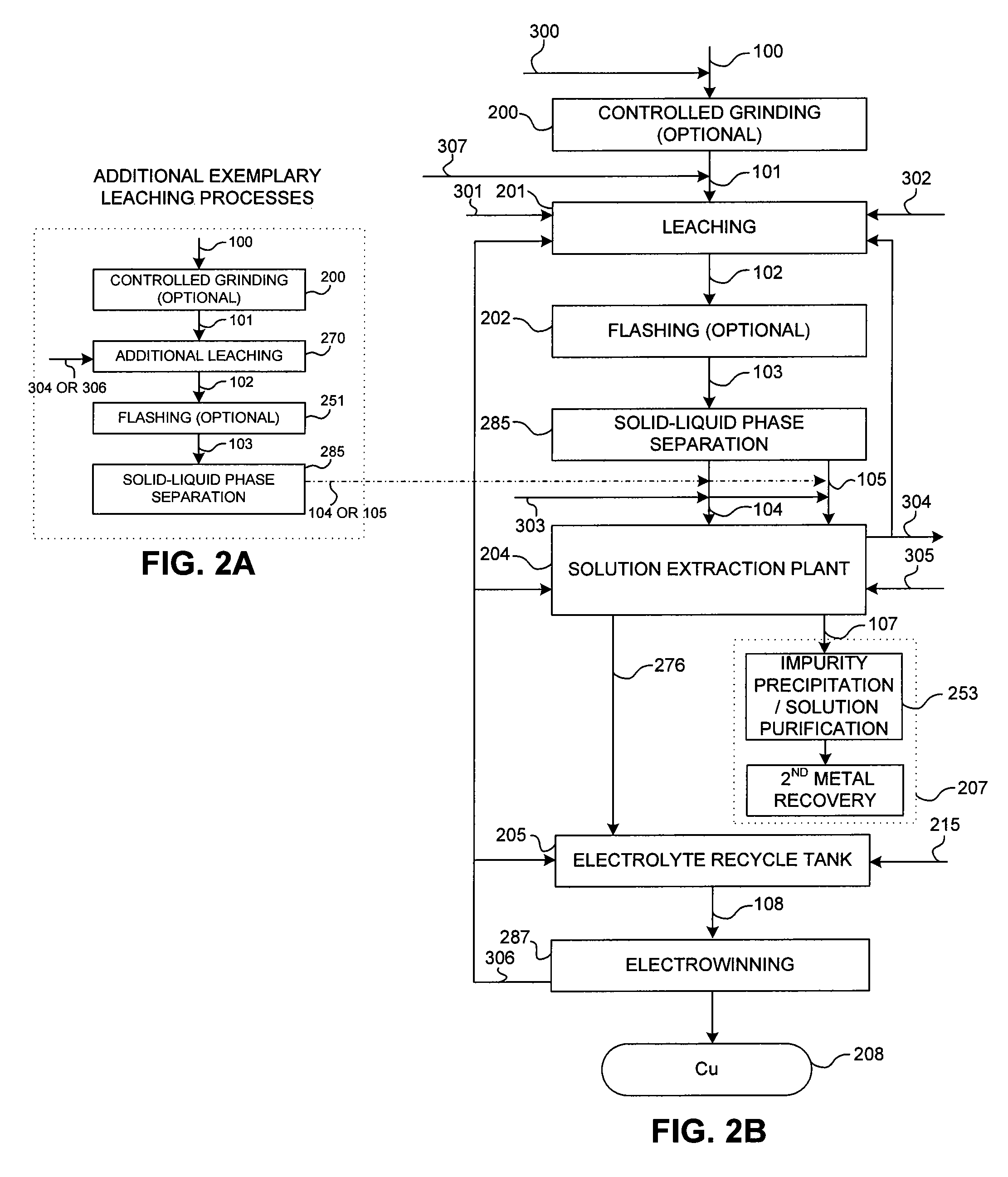
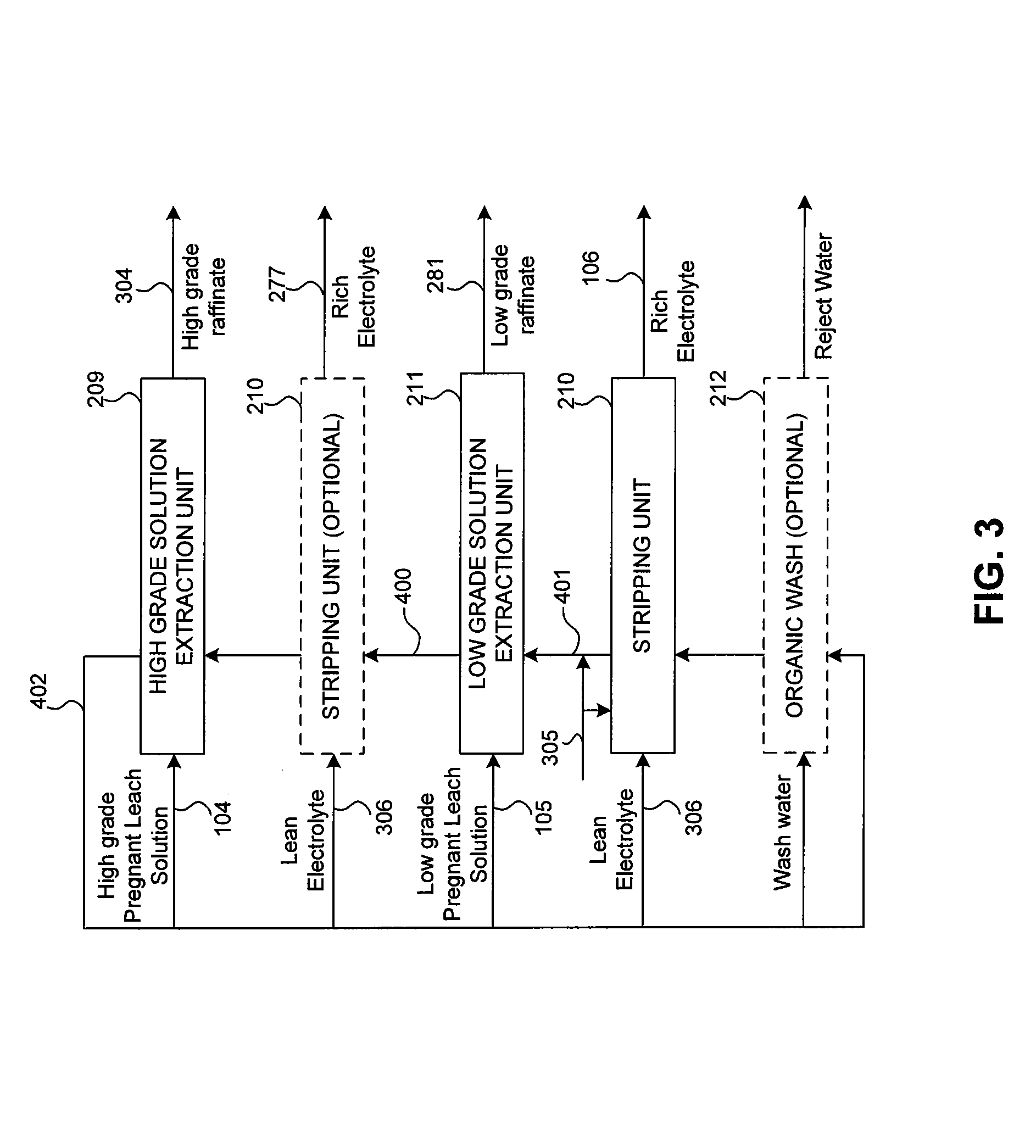
[0015]The detailed description of exemplary embodiments of the invention herein shows various exemplary embodiments and the best modes, known to the inventors at this time. These exemplary embodiments and modes are described in sufficient detail to enable those skilled in the art to practice the invention and are not intended to limit the scope, applicability, or configuration of the invention in any way. Rather, the following disclosure is intended to teach both the implementation of the exemplary embodiments and modes and any equivalent modes or embodiments that are known or obvious to those of reasonable skill in the art. Additionally, all included figures are non-limiting illustrations of the exemplary embodiments and modes, which similarly avail themselves to any equivalent modes or embodiments that are known or obvious to those of reasonable skill in the art.

[0016]Various embodiments of the present invention exhibit significant advancements over prior art processes, particular...


PUM

PropertyMeasurementUnit
temperatureaaaaaaaaaa
partial pressureaaaaaaaaaa

Abstract

The present invention relates generally to a process for controlled leaching and sequential recovery of two or more metals from metal-bearing materials. In one exemplary embodiment, recovery of metals from a leached metal-bearing material is controlled and improved by providing a high grade pregnant leach solution (“HGPLS”) and a low grade pregnant leach solution (“LGPLS”) to a single solution extraction plant comprising at least two solution extractor units, at least two stripping units, and, optionally, at least one wash stage.

Description

FIELD OF INVENTION[0001]The present invention relates generally to a process for controlled leaching and sequential recovery of two or more metals from metal-bearing materials. In one exemplary embodiment, recovery of metals from a leached metal-bearing material is controlled and improved by providing a high grade pregnant leach solution (“HGPLS”) and a low grade pregnant leach solution (“LGPLS”) to a single solution extraction plant comprising at least two solution extractor units, at least two stripping units, and, optionally, at least one wash stage.BACKGROUND OF THE INVENTION[0002]Hydrometallurgical treatment of metal-bearing materials, such as metal ores, metal-bearing concentrates, and other metal-bearing substances, has been well established for many years. Moreover, leaching of metal-bearing materials is a fundamental process utilized to extract metals from metal-bearing materials. In general, the first step in this process is contacting the metal-bearing material with an aq...

Claims


Application Information

Patent Timeline
Patent Type & Authority Patents(United States)
IPC IPC(8): C21B15/00
CPCC22B3/0005C22B3/20C22B15/0095C22B15/0084C22B15/0071Y02P10/20C22B3/26
Inventor SAVAGE, BARBARA J.MEADOWS, DAVID G.HAZEN, WAYNE W.
Owner FREEPORT MCMORAN COPPER & GOLD INC
Why Eureka
Try Eureka