Fuel control system and associated method

a technology of fuel control system and fuel control method, which is applied in the direction of electrical control, process and machine control, etc., can solve the problems of inability to fully use alternate fuels, inability to adapt to the changing inability to meet the needs of the user, etc., to facilitate the use of primary fuels, simple and inexpensive, easy to adapt

Active Publication Date: 2011-08-30
GILBARCO
View PDF44 Cites 37 Cited by
  • Summary
  • Abstract
  • Description
  • Claims
  • Application Information

AI Technical Summary

Benefits of technology

[0016]Thus, the fuel control system of the present invention can be used to facilitate the use of a primary fuel and an alternate fuel in an internal combustion engine. The present invention can be simple and inexpensive, and in some cases, can be easily adaptable to vehicles designed to operate using a primary fuel. Thus, the present invention can be used to convert such an engine to one that is capable of using both a primary fuel source and an alternate fuel source.

Problems solved by technology

However, practical applications have demonstrated that full-time use of these alternate fuels is not desirable.
For instance, at low temperatures the viscosity of some of these alternate fuels is not optimal for use in an engine designed to run on primary fuel.
If left in an idle engine to cool, the alternate fuel also has a tendency to increase in viscosity and thus congeal inside the fuel delivery components.
This abrupt switching of fuels can result in abrupt changes in engine behavior.
Reduced or unacceptable performance may be experienced at or near the switching transition point, and potential utilization of alternate fuel may be forfeited during intermediate conditions by forcing premature switching of fuel to mitigate transition behavior.
As a result, conventional alternate fuel systems typically suffer from difficulty in integration, do not accommodate grade loading, exhibit poor performance at fuel type transition points, must underutilize alternate fuel, and are not applicable to engine types intolerable of 100% alternate fuel mixtures.

Method used


Image

  • Fuel control system and associated method
  • Fuel control system and associated method
  • Fuel control system and associated method

Examples


Embodiment Construction

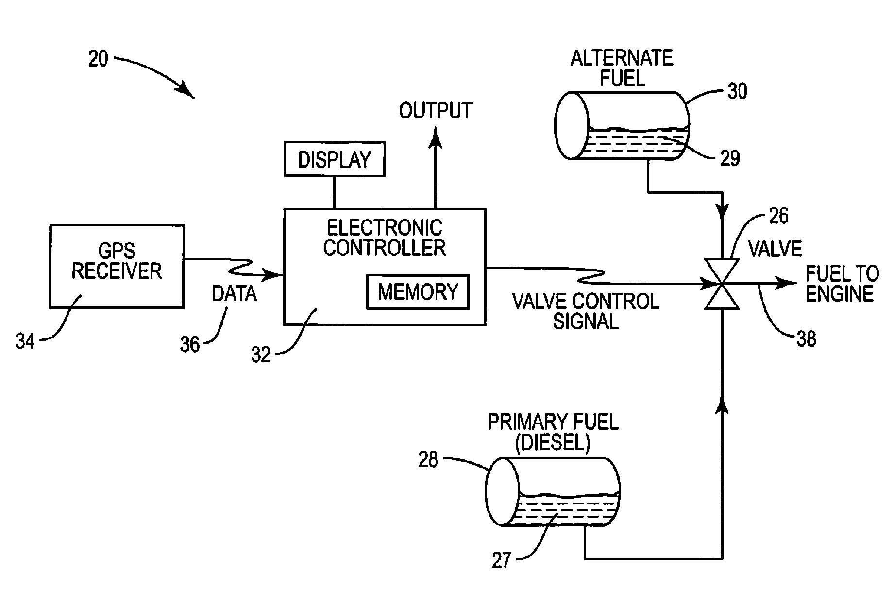
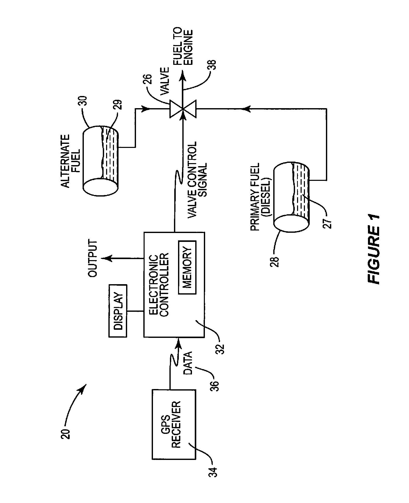
[0034]The present inventions now will be described more fully hereinafter with reference to the accompanying drawings, in which some, but not all embodiments of the inventions are shown. Indeed, these inventions may be embodied in many different forms and should not be construed as limited to the embodiments set forth herein; rather, these embodiments are provided so that this disclosure will satisfy applicable legal requirements. Like numbers refer to like elements throughout.

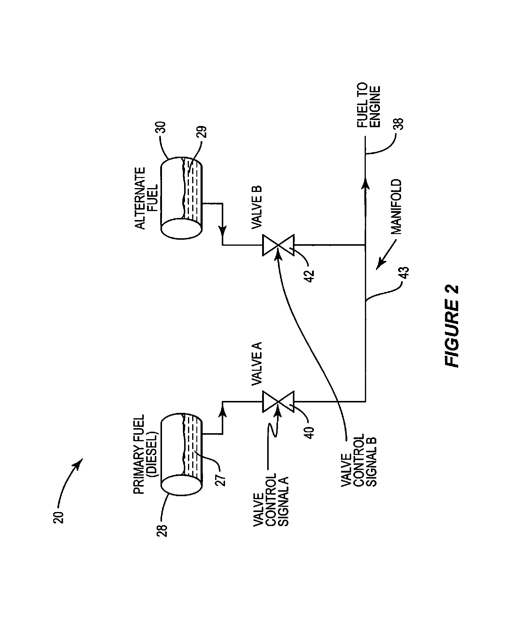
[0035]The present invention provides a fuel control system that can generally be used as an inexpensive and easily adaptable solution for selectively delivering a primary fuel and an alternate fuel for operation of an engine. For the purposes of this application, the term “selectively deliver,” and other forms thereof, is defined as providing an engine with 100% primary fuel and 0% alternate fuel, 100% alternate fuel and 0% primary fuel, or any mixture of primary fuel and alternate fuel. As will be discussed i...


PUM


Abstract

A fuel control system and method for providing fuel to an internal combustion engine are provided. The fuel control system generally includes at least one valve device structured to deliver a fuel supply to the engine, a first fuel source structured to provide a primary fuel to the valve device, a second fuel source structured to provide an alternate fuel to the valve device, and an electronic controller structured to control the valve device. The electronic controller controls the valve device as a function of various data to selectively deliver the primary fuel and the alternate fuel to generate a fuel supply, e.g. as a mixture of the two fuels. The data used to control the fuel supply may include GPS data, engine data, environmental data, and / or other operational data.

Description

BACKGROUND OF THE INVENTION[0001]1) Field of the Invention[0002]The present invention relates to fuel systems for internal combustion engines and more particularly to fuel systems that provide both primary fuel and alternate fuel to an internal combustion engine.[0003]2) Description of Related Art[0004]For a variety of reasons, most of which relate to environmental and alternative energy pursuits, certain primary fuel engines, such as diesel engines, can be made to accommodate alternate fuels, such as straight vegetable oil (SVO), “biodiesel,” and other fuel oils (hereinafter “alternate fuels”). However, practical applications have demonstrated that full-time use of these alternate fuels is not desirable. For instance, at low temperatures the viscosity of some of these alternate fuels is not optimal for use in an engine designed to run on primary fuel. The alternate fuel should be heated up to a temperature that will allow it to easily pass through the fuel delivery system. If left ...

Claims


Application Information

Patent Timeline
Patent Type & Authority Patents(United States)
IPC IPC(8): F02D41/00
CPCF02D19/0605F02D19/08F02D41/0025F02M37/0064F02D19/061F02D19/0618F02D19/0652F02D19/0689F02D19/0692F02D19/0694F02D19/081F02D19/0628F02D41/021F02D2200/701Y02T10/36Y02T10/30
Inventor WILLIAMS, RODGER K.PAYNE, EDWARD
Owner GILBARCO
Why Eureka
Try Eureka