
Over-wing traveling-wave axial flow plasma accelerator

a plasma accelerator and traveling wave technology, applied in the direction of air-flow influencers, machines/engines, transportation and packaging, etc., can solve the problems of inefficient structural efficiency of the flap surface, complex mechanical flap surface actuation systems, and heavy hydraulic or electric actuation systems

Inactive Publication Date: 2011-08-30
LOCKHEED MARTIN CORP
View PDF41 Cites 17 Cited by
  • Summary
  • Abstract
  • Description
  • Claims
  • Application Information

AI Technical Summary

Benefits of technology

This approach reduces aircraft weight, drag, and structural heating while improving flight performance by enabling more efficient aerodynamic control without the need for traditional mechanical systems, allowing for reduced vehicle size and improved maneuverability.

Problems solved by technology

Aircraft typically require complex, heavy, mechanical flap surface actuation systems for vehicle flight stability and control.
While very effective aerodynamically, these flap-based controls require powerful and heavy hydraulic or electric actuation systems to move the flap effectors.
Furthermore, the flap surfaces are structurally inefficient in that they introduce discontinuities in the airframe surface which requires additional structural weight for support.
Additionally, exotic shapes may cause excessive propulsion performance losses.
Flow field detachments may produce increased body drag and aerodynamic buffeting.
All of which compromise the integrity and capability of these aircraft.
Components may also be repositioned to non-optimal positions to reduce these stresses.
However, these situations often result in reduced vehicle performance.
Similarly, adding structural weight to support increased stress loads also results in reduced vehicle performance.
The consequences of such solutions compromise vehicle capability.

Method used


Image

  • Over-wing traveling-wave axial flow plasma accelerator
  • Over-wing traveling-wave axial flow plasma accelerator
  • Over-wing traveling-wave axial flow plasma accelerator

Examples


Embodiment Construction

[0019]Preferred embodiments of the present invention are illustrated in the figures like numerals being used to refer to like and corresponding parts of the various drawings.

[0020]Embodiments disclosed herein provide a plasma flow accelerated through an electric field to manipulate a fluid flow over a surface. These embodiments may be applied to a fully fixed, non-articulating geometry vehicle that substantially eliminates or reduces disadvantages and problems associated with previous designs. The invention is not limited to fixed geometry vehicles. Helicopter and variable sweep aircraft are examples of articulating geometry applications.

[0021]In physics and chemistry, plasma (also called an ionized gas) is an energetic state of matter in which some or all of the electrons in the outer atomic orbital rings have become separated from the atom. Excitation of plasma requires partial ionization of neutral atoms and / or molecules of a medium. There are several ways to cause ionization inc...


PUM


Abstract

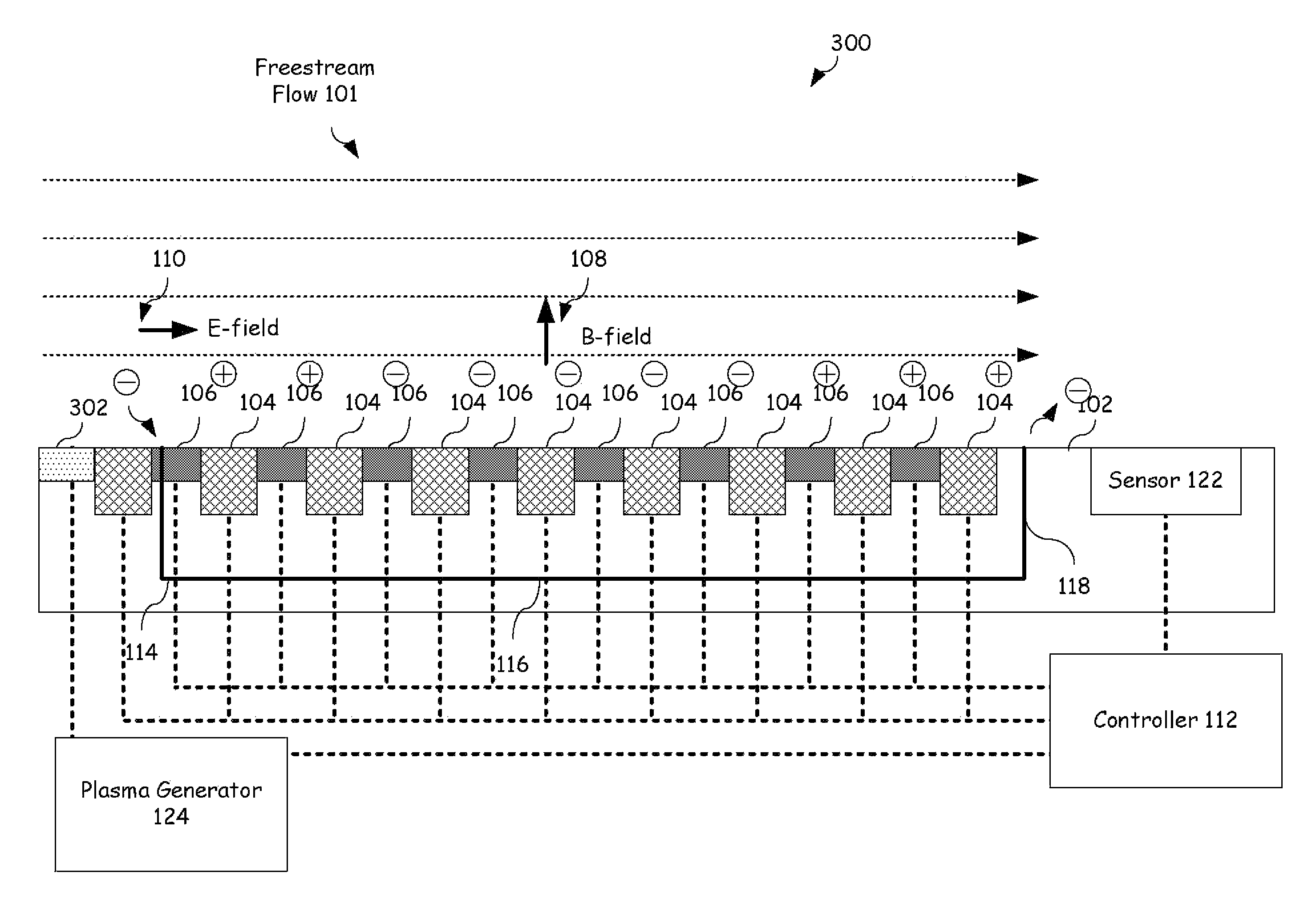
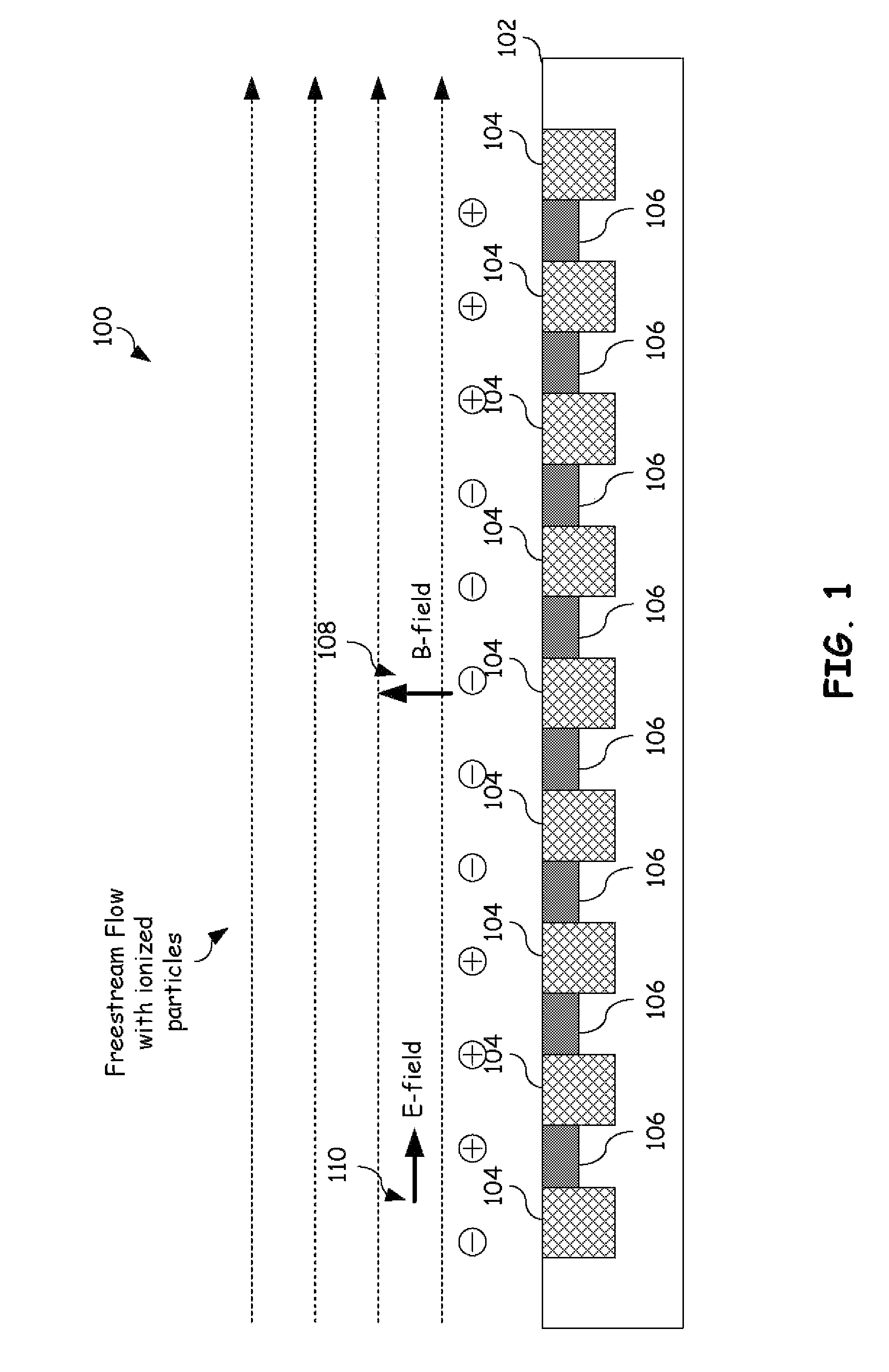
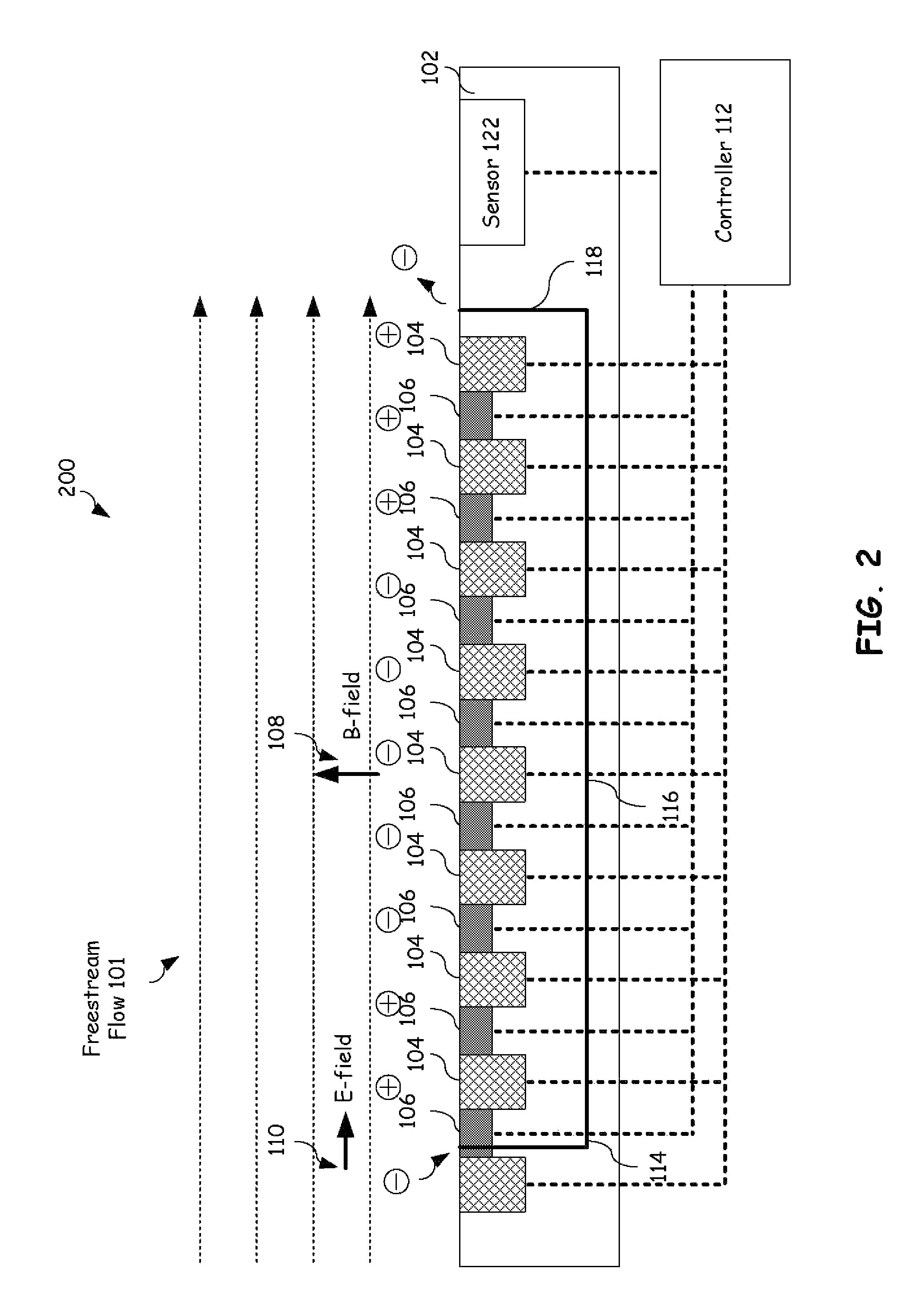
A method to manipulate a fluid flow over a surface is provided. This method may be used to reduce drag, improve the lift to drag (L / D) ratio, attach fluid flow, or reduce flow noise at the surface. This involves flowing a fluid over the surface wherein the fluid contains positively charged ions and electrons. An electric field accelerates ions and electrons in directions parallel to the electric field. A magnetic field at the surface redirects ions and electrons based on their velocity and charge. The magnetic field imparts little force on the relatively heavy and slow moving positive ions but has a significant impact on the relatively fast moving, light weight electrons. This results in a non-zero net change in the total momentum of the positive ions and electrons allowing thrust to be realized. This thrust may be sufficient for vehicle propulsion or manipulation of the fluid flow around the vehicle. Pulsed and traveling wave implementations of this body force enable exploitation of frequencies to which the flow is sensitive, improving effectiveness of this method.

Description

TECHNICAL FIELD OF THE INVENTION[0001]The present invention relates generally to manipulation of fluid flow and more particularly, a system and method for manipulating an ionized fluid flow over a surface.BACKGROUND OF THE INVENTION[0002]Aircraft typically require complex, heavy, mechanical flap surface actuation systems for vehicle flight stability and control. While very effective aerodynamically, these flap-based controls require powerful and heavy hydraulic or electric actuation systems to move the flap effectors. Furthermore, the flap surfaces are structurally inefficient in that they introduce discontinuities in the airframe surface which requires additional structural weight for support. Current emphasis for next-generation aircraft require a dramatic reduction in airframe weight and cost while maintaining performance and capability.[0003]Active flow control involves modification of the turbulent structure of eddies in most complex flows with the intent to improve aerodynamic...

Claims


Application Information

Patent Timeline
Patent Type & Authority Patents(United States)
IPC IPC(8): B64C21/00
CPCB64C23/005F03H1/00F15D1/12H05H1/54F05D2270/172Y02T50/166B64C2230/12Y02T50/10
Inventor MCCLURE, PAUL D.CHASE, CHARLES J.
Owner LOCKHEED MARTIN CORP
Learn More