
Infrared tracer composition and tracer projectile

a tracer and composition technology, applied in the field of infrared, can solve the problems of emitted visible light, detrimentally emitted significant levels of infrared light, and it is difficult to track the projectile path of the tracer projectile when using infrared detection

Inactive Publication Date: 2011-08-30
KILGORE FLARES
View PDF4 Cites 14 Cited by
  • Summary
  • Abstract
  • Description
  • Claims
  • Application Information

AI Technical Summary

Benefits of technology

[0011]Various refinements exist of the features noted in relation to one or more of the above-described aspects of the present invention. Further features may also be incorporated into one or more of those aspects as well. These refinement...

Problems solved by technology

One drawback of some conventional tracers utilized in combat is that they emit a significant amount of visible light, which may enable an enemy to discern a location of the source of the tracer projectile.
Numerous conventional tracer compositions are capable of emitting varying levels of visible light but detrimentally emit significant levels of infrared light.
Conversely, other conventional tracer compositions fail to emit sufficient levels of infrared light, thus, making it difficult to track the projectile path of the tracer projectile when using infrared detection.
For instance, if the intensity of the infrared emissions is too great, Generation III night vision goggles may malfunction (e.g., momentary shutdown referred to as a “bloom”) causing the viewer to be temporarily blinded.

Method used


Image

  • Infrared tracer composition and tracer projectile
  • Infrared tracer composition and tracer projectile
  • Infrared tracer composition and tracer projectile

Examples


Embodiment Construction

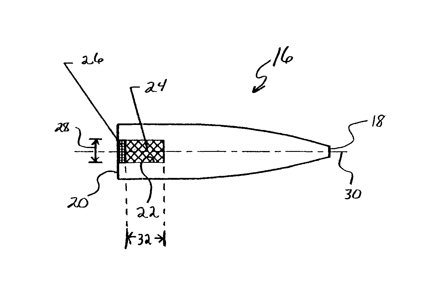
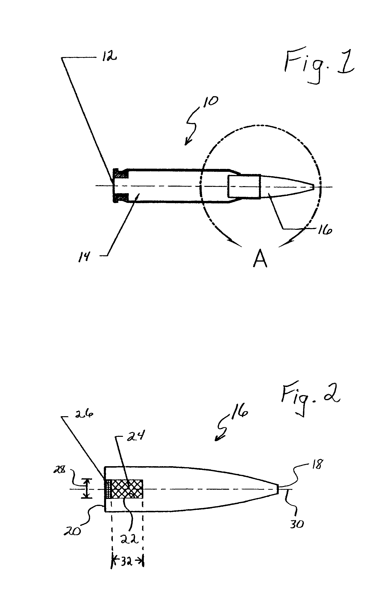
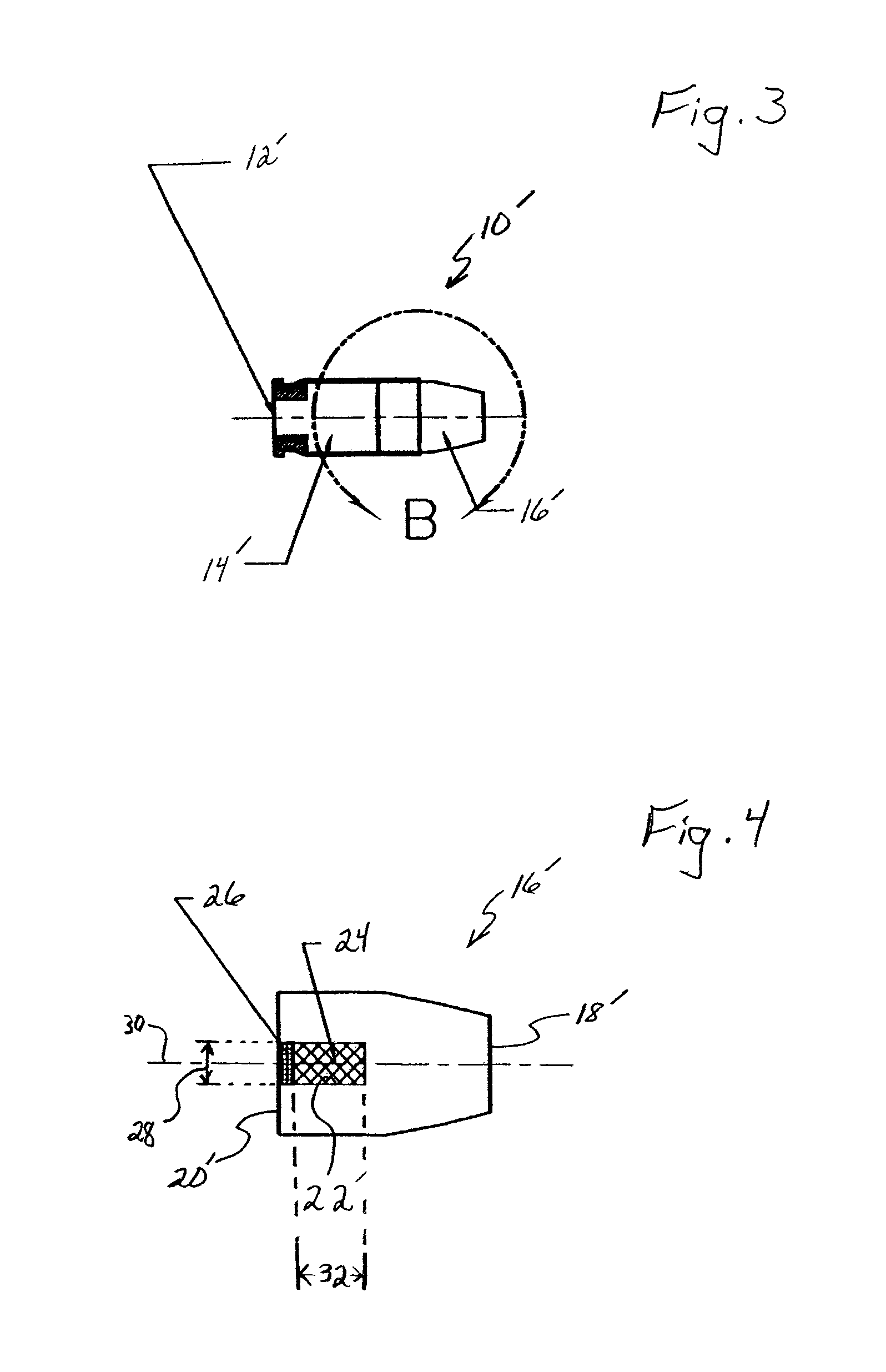
[0017]The present invention will now be described in relation to the accompanying drawings, which at least assist in illustrating the various pertinent features thereof. FIG. 1 shows a rifle cartridge 10 that includes a primer 12, casing 14, and a projectile 16. The primer 12 may be any appropriate primer, may be any appropriate size, and may be made of any appropriate material. Likewise, the casing 14 may exhibit any of a number of appropriate designs / sizes and may be made of any of a number of appropriate materials. While not illustrated, the casing 14 of the rifle cartridge 10 generally has an appropriate propellant housed therein. This propellant is generally ignited (via an appropriate activation of the primer 12) to provide a propulsive force to the projectile 16 which causes an ejection of the projectile 16 from the casing 14.

[0018]The projectile 16 of the rifle cartridge 10 is illustrated in detail in FIG. 2. As shown, the projectile 16 has a leading end 18 and an opposing t...


PUM


Abstract

The present invention is directed to a tracer composition for tracer bullets and other projectiles. One preferred formula of the tracer composition generally includes about 58 parts by weight of magnesium, about 38 parts by weight of polytetraflouroethylene, about 4 parts by weight of acrylic rubber, and a burn rate stabilizer such as about 1.5 parts by weight of carbon black or graphite. Tracer bullets including the tracer composition of the invention tend to exhibit a projectile path that is almost unnoticeable to the naked eye but quite visible through the use of equipment detecting energy in the near infrared range.

Description

RELATED APPLICATIONS[0001]This is a divisional application which claims the benefit of U.S. patent application Ser. No. 11 / 023,078 which was filed on Dec. 27, 2004 and is hereby incorporated by reference.STATEMENT REGARDING SPONSORED RESEARCH OR DEVELOPMENT[0002]Not applicable.REFERENCE TO A MICROFICHE APPENDIX[0003]Not applicable.FIELD OF THE INVENTION[0004]The present invention is related to small caliber tracer projectiles or bullets, each of which may be expelled from a firearm such as a rifle or pistol. More particularly, the present invention relates to a tracer composition for small caliber projectiles bullets that, when ignited, emit a controlled amount of near infrared light to allow a flight path of the projectile to be tracked without causing a “bloom” in Generation III night vision systems.BACKGROUND OF THE INVENTION[0005]Tracer projectiles are often utilized in combat and warfare training to provide a visual trace of the path of a projectile. For instance, tracers may b...

Claims


Application Information

Patent Timeline
IPC IPC(8): C06B33/00D03D43/00C06B29/02D03D23/00C06B27/00
CPCC06B27/00C06C15/00F42B12/38
Inventor HERBAGE, DAVID W.NEUHAUSER, ROY L.SMITH, BARRY N.
Owner KILGORE FLARES
Learn More