Inclined carrier transferring apparatus

a transfer apparatus and carrier technology, applied in the direction of conveyors, transportation and packaging, vacuum evaporation coating, etc., can solve the problems of relative large size and volume of the carrier, uneven layer in the processed substrate, etc., to increase the evenness of the layer on the substrate, the effect of minimizing the lateral movement of the carrier

Active Publication Date: 2011-08-30
AVACO +2
View PDF4 Cites 7 Cited by
  • Summary
  • Abstract
  • Description
  • Claims
  • Application Information

AI Technical Summary

Benefits of technology

[0014]An object of the present invention is to provide an inclined carrier transferring apparatus that minimizes lateral movement of the carrier during the transferring operation.
[0015]Another object of the present invention is to provide an inclined carrier transferring apparatus that allows a substrate to be securely loaded on a carrier for the transferring operation.
[0016]A further object of the present invention is to provide an inclined carrier transferring apparatus that increases the evenness of a layer on a substrate.

Problems solved by technology

The relatively large size and volume of the carrier has been found to be a source of difficulty during the substrate manufacturing process.
This type of the carrier transferring apparatus has the disadvantage in that the central portion of the substrate tends to protrude outward due to the vertical orientation of the substrate, which may produce an uneven layer in the processed substrate.
Also, when the substrate is loaded on the carrier, it may be unstable.

Method used


Image

  • Inclined carrier transferring apparatus
  • Inclined carrier transferring apparatus
  • Inclined carrier transferring apparatus

Examples


Embodiment Construction

[0035]Reference will now be made in detail to the preferred embodiments of the present invention, examples of which are illustrated in the accompanying drawings. Wherever possible, the same reference numbers will be used throughout the drawings to refer to the same or like parts.

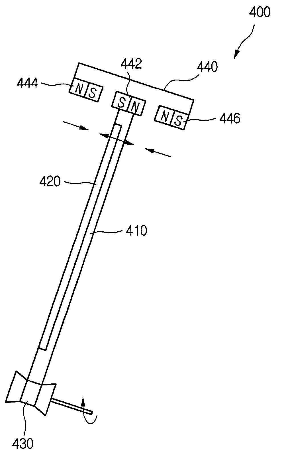
[0036]Turning now to FIG. 4, a carrier transferring apparatus 400 is provided to transfer a carrier 410 tilted at a predetermined angle. The carrier 410 includes a recess that supports a substrate 420. Rollers 430 are disposed at a predetermined slant or incline and are provided at the lower portion of the carrier 410, in order to transfer the carrier 410. When the rollers 430 are driven, the carrier 410 is transferred in a specified direction. In other embodiments (not shown), the rollers 430 may be replaced with a conveyer including at least one belt.

[0037]By transferring the carrier 410 while the carrier 410 is positioned at an incline, the substrate 420 positioned on the carrier 410 is not transferred in...


PUM

PropertyMeasurementUnit
distanceaaaaaaaaaa
magnetic forceaaaaaaaaaa
magneticaaaaaaaaaa

Abstract

An inclined carrier transferring apparatus for use inline sputtering equipment. The inclined carrier transferring apparatus includes rollers and a guiding portion. The rollers transfer and support the bottom of a carrier. The guiding portion is installed diagonally with respect to the rollers, to support the top of the carrier in a non-contact manner.

Description

CROSS-REFERENCE TO RELATED PATENT APPLICATION[0001]This application claims the benefit of Korean Patent Application No. 10-2005-0053987, filed on Jun. 22, 2005, in the Korean Intellectual Property Office, the disclosure of which is incorporated herein by reference in its entirety.FIELD OF THE INVENTION[0002]The present invention relates to a substrate transferring apparatus for use in a sputtering apparatus, and more particularly, to an inclined carrier transferring apparatus for a sputtering equipment.DESCRIPTION OF THE RELATED ART[0003]In order to manufacture liquid crystal display devices (LCD) and other types of flat panel display devices, many thin film deposition, photolithography, and etching processes must be performed. Sputtering is generally used to deposit thin films, especially when forming a black matrix, a metal layer or a transparent electrode on the substrate.[0004]Sputtering equipment for thin film deposition may be divided into cluster-type sputtering equipment and...

Claims


Application Information

Patent Timeline
Patent Type & Authority Patents(United States)
IPC IPC(8): C23C14/34C23C16/00
CPCC23C14/50C23C14/568Y10S414/139B65G47/94H01L21/68
Inventor KIM, SUNG EUNLIM, TAE HYUNYOO, KWANG JONGYUN, BYUNG HANMOON, YANG SIK
Owner AVACO
Why Eureka
Try Eureka