Methods, systems and apparatus for regulating frequency of generated power using flywheel energy storage systems with varying load and/or power generation

a technology of energy storage system and generated power, which is applied in the direction of electric generator control, dynamo-electric converter control, transportation and packaging, etc., can solve the problems of increasing frequency, reducing the power generation capacity of the power generation system, and constantly challenging the electric generation and distribution system with a mismatch between load and power being generated. , to achieve the effect of reducing the amount of power

Inactive Publication Date: 2011-08-30
BEACON POWER LLC
View PDF9 Cites 76 Cited by
  • Summary
  • Abstract
  • Description
  • Claims
  • Application Information

AI Technical Summary

Benefits of technology

[0021]In more particular embodiments, such a frequency control method includes controlling the operation of each of the flywheel energy storage systems so as to reduce the amount of power being outputted to the electrical distribution network by the energy storage sub-system a determined amount, when the total power being outputted by the one or more power sources exceeds the total load imposed by the one or more loads and the line losses associated with the transmission and distribution network. In addition, the flywheel energy storage systems can be operated so as to draw power from the distribution network when there is an excess of electrical power that is being generated. In this way, the energy storage sub-system can absorb at least a portion of the excess electrical energy being generated.
[0025]In further embodiments, a frequency control methodology according to the present invention includes electrically coupling a plurality of energy storage sub-systems to the electrical distribution network and separately controlling each of the energy storage sub-systems so as to one of deliver electrical power to the electrical distribution network or absorb electrical power from the electrical distribution network. In further embodiments, such a methodology includes controllably operating the flywheel energy storage systems of each of the plurality of energy storage sub-systems so as to alternatively deliver electrical power to the electrical distribution network and absorb electrical power from the electrical distribution network. In this way, one can use the flywheel energy storage systems that have given up energy to the electrical distribution network as an energy sink for absorbing the excess electrical power being generated.

Problems solved by technology

Because of such short-term variations that occur in the electrical load imposed on the electrical generation and distribution system and because the ability of a generator to follow such load variations is typically much slower than the time period of the load variation, the electrical generation and distribution system is constantly challenged with a mismatch between the load and the power being generated.
Because of the time lag associated with increasing or decreasing power by a given power generator, however, the effect on power generation by the signal being in outputted is delayed in time.
Control areas are not able and not required to perfectly match generation and load.
Over-generation at such times, however, would further increase frequency and lead to a bad CPS1 value.
Although such a mode of operation is achievable with some types of power generating facilities, such a mode of operation has a negative impact on the life and overall deficiency of a typical fossil-fueled electrical generator (e.g., gas turbine powered electric generator).
While batteries are used to form an un-interruptible power supply, cyclical operation of a battery such as that undergone when performing fine tune regulation of AC frequency can prove to be damaging to the battery, including affecting operational life as well as the battery storage capacity.
Such reserves are typically capable of providing larger blocks of power as a complement to the power sources utilized for fine tuning of the AC frequency, however, such reserves typically take a longer time to reach full capacity (e.g., on the order of 10-15 or 30-60 minutes) and thus are not practically speaking useable for the fine tune regulation of AC frequency.

Method used


Image

  • Methods, systems and apparatus for regulating frequency of generated power using flywheel energy storage systems with varying load and/or power generation
  • Methods, systems and apparatus for regulating frequency of generated power using flywheel energy storage systems with varying load and/or power generation
  • Methods, systems and apparatus for regulating frequency of generated power using flywheel energy storage systems with varying load and/or power generation

Examples


Embodiment Construction

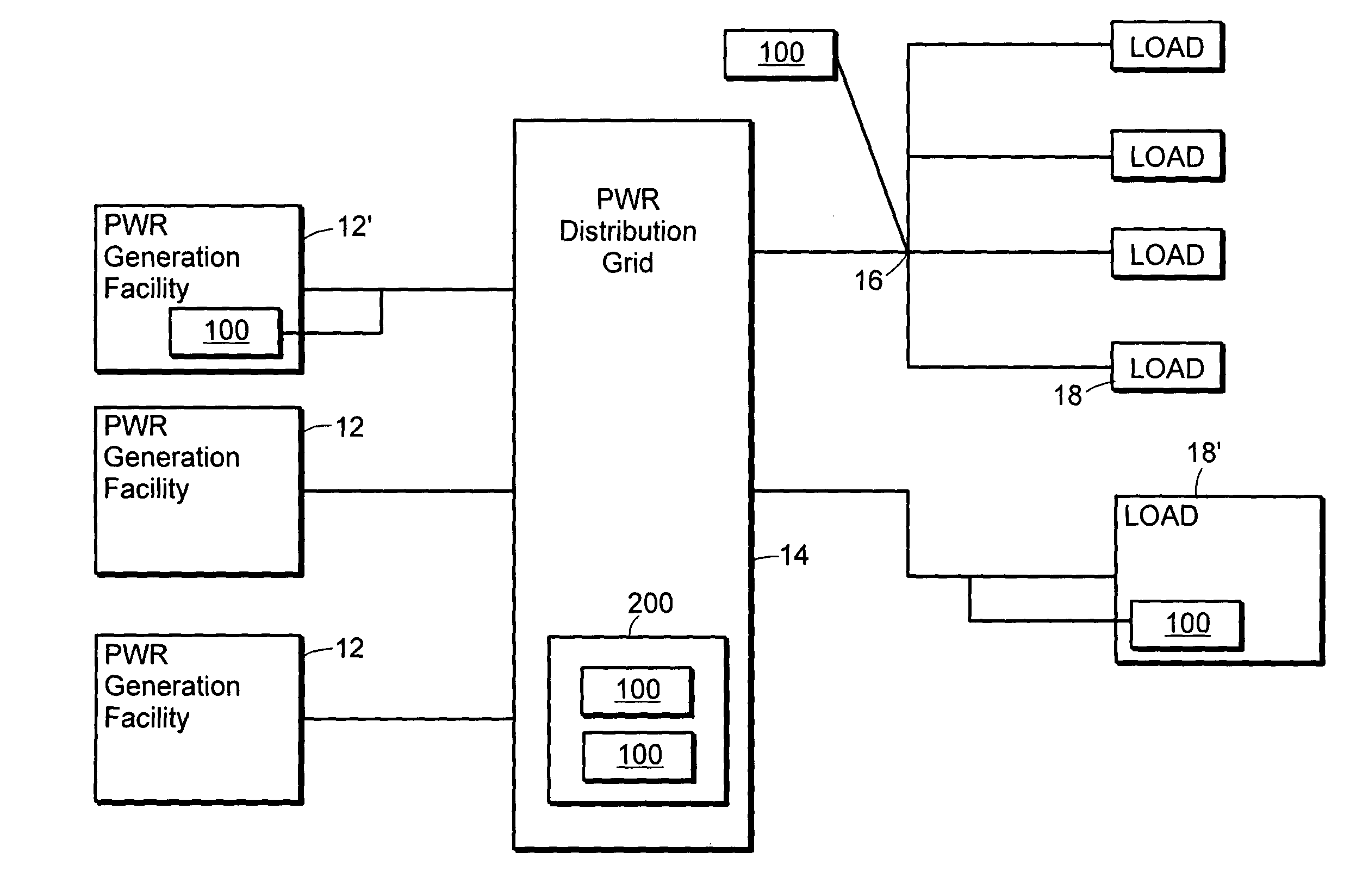
[0055]Referring now to the various figures of the drawing wherein like reference characters refer to like parts, there is shown in FIG. 4 a block diagram of an exemplary power generation and distribution system 10 coupled to any one of a number of system loads 18, 18′ (e.g., loads imposed by customers or users) and which illustrates various placements of an FESS array 100 of the present invention within such a system. The exemplary power generation and distribution system 10 includes one or more power generation facilities 12, 12′ that are selectively and electrically coupled to the power distribution grid 14 using any of a number of techniques known to those skilled in the art. Such power generation facilities 12, 12′ includes fixed sites, such as fixed fossil-fuel or nuclear power generation facilities, hydroelectric power generation facilities; battery farms; pumped hydro power generation facilities; diesel generators, or green (e.g., wind powered or solar powered) power generati...


PUM


Abstract

Featured are methods for regulating the AC frequency of the electrical power be supplied on an electrical distribution system or grid. Such a method includes electrically coupling an energy storage sub-system to the electrical distribution network, where the energy storage sub-system includes one or more flywheel energy storage systems. Also featured as devices, systems and apparatuses embodying such methodologies or for use in implementing such methodologies of the present invention.

Description

FIELD OF INVENTION[0001]The present invention relates to methods, systems and apparatuses for regulating the frequency of the generated power when the load and / or generated power is subject to variation as a function of time, in particular methods, systems and apparatuses for regulating frequency of generated electrical power when the load and / or power being generated varies as a function of time and more particularly, methods, systems and apparatuses for regulating frequency of generated electrical power when the load and / or power being generated varies as a function of time using one or more flywheel energy storage systems.BACKGROUND OF THE INVENTION[0002]In the United States, electric power is generated so as to provide an AC voltage in a desired voltage range and at a desired frequency, 60 Hz. Such power is generated by anyone of a number of power generation plants or power generation methods including for example large fixed electrical power generation facilities using fossil f...

Claims


Application Information

Patent Timeline
Patent Type & Authority Patents(United States)
IPC IPC(8): H02J3/38H02J3/00H02H7/06H02JH02P9/00
CPCH02J3/30Y02E60/16
Inventor CAPP, F. WILLIAMLAZAREWICZ, MATTHEW L.ARSENEAUX, A. JAMESDRESENS, PAULROJAS, HERNAN ALEX
Owner BEACON POWER LLC
Why Eureka
Try Eureka