Optical system and method for use in projection systems

a projection system and optical system technology, applied in optics, condensers, instruments, etc., can solve the problems of inability to provide high optical power with relatively low power consumption, inability to provide small physical size with low overall price of light source, and too expensive laser light source composed of a single laser diode for light source applications, etc., to improve and optimize projection system, reduce the physical size of slm, and fast pulse mode drive operation

Inactive Publication Date: 2011-08-30
EXPLAY
View PDF13 Cites 80 Cited by
  • Summary
  • Abstract
  • Description
  • Claims
  • Application Information

AI Technical Summary

Benefits of technology

[0011]The present invention provides a novel approach for the light source aspect and the light propagation aspect (optical path) to dramatically optimize the optical system performance (e.g. projection systems), costs and size; as well as a low cost fabrication method for optical elements with total control on the light beam properties.
[0038]The combination of several light sources in a single medium, along with fast pulse mode drive operation to obtain lower consumption, higher output optical intensity and speckle reduction, with sets of light groups (laser die arrays, LED die, VCSEL arrays) and a sequencing mechanism into a single light module is a significant improvement over the state of the art.

Problems solved by technology

The problem still keeping LEDs and lasers from becoming key light sources in the illumination / multimedia industry is the inability to provide high optical power with relatively low power consumption, as well as inability to provide small physical size with overall low price of the light source, which is also due to the low efficiency of today's projection system that enforces high power sources.
A laser light source composed of a single laser diode is too expensive for light source applications due to the method of fabrication and the high power out put required.

Method used


Image

  • Optical system and method for use in projection systems
  • Optical system and method for use in projection systems
  • Optical system and method for use in projection systems

Examples


Embodiment Construction

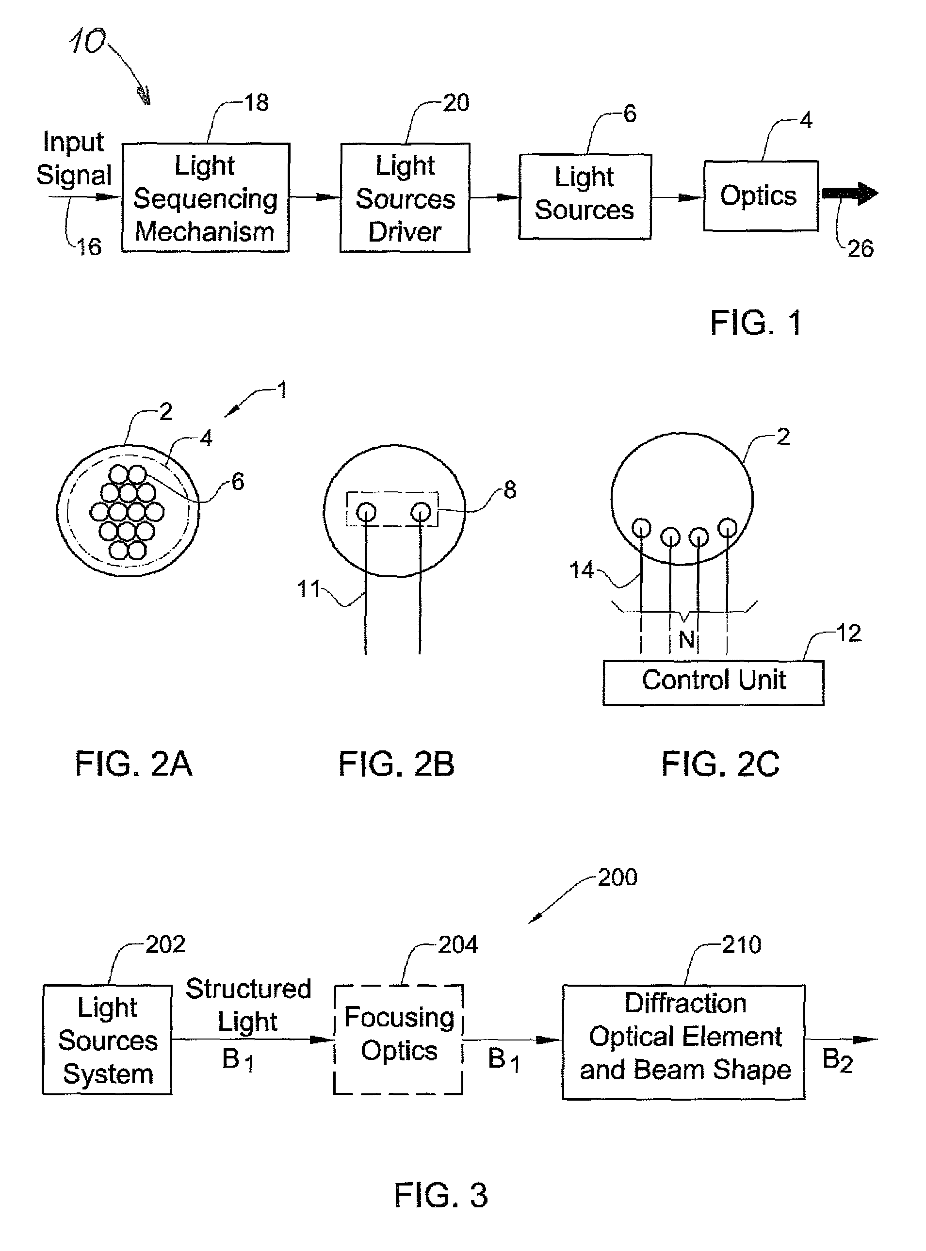
[0059]Referring to FIG. 1, there is illustrated, by way of a block diagram, a light source system 10 of the present invention. The system 10 includes an arrangement of micro light sources 6; a focusing optics (light collecting / directing optics) 4; a light source driver assembly 20; and a processor preprogrammed for carrying out a light sequencing mechanism 18.

[0060]FIGS. 2A to 2C more specifically illustrate the possible implementations of the light source system of FIG. 1.

[0061]FIG. 2A shows a top view of a light source module 1 formed by a plurality of N micro light sources 6 all carried by a common substrate 2, and the light collecting / directing optics 4 located over the plurality of micro light sources 6. In the present example, the optics 4 includes a single collection lens for collecting light generated by all the micro light sources 6 and directing the collected light outwards in a parallel manner relatively unified. It should be noted that additional optics could be added up...


PUM


Abstract

An optical system and method are presented to produce a desired illuminating light pattern. The system comprises a light source system configured and operable to produce structured light in the form of a plurality of spatially separated light beams; and a beam shaping arrangement. The beam shaping arrangement is configured as a diffractive optical unit configured and operable to carry out at least one of the following: (i) combining an array of the spatially separated light beams into a single light beam thereby significantly increasing intensity of the illuminating light; (ii) affecting intensity profile of the light beam to provide the illuminating light of a substantially rectangular uniform intensity profile.

Description

FIELD OF THE INVENTION[0001]This invention is generally in the field of optical systems and methods, and relates to an optimized light source and beam shaping system and method suitable for use in projections systems.BACKGROUND OF THE INVENTION[0002]As light source technology evolves, light emitting diodes (LEDs) and lasers are being used in ever growing applications. These types of light sources, due to their increased optical efficiency and low power consumption are starting to replace standard light sources such as halogen, florescent, etc.[0003]The problem still keeping LEDs and lasers from becoming key light sources in the illumination / multimedia industry is the inability to provide high optical power with relatively low power consumption, as well as inability to provide small physical size with overall low price of the light source, which is also due to the low efficiency of today's projection system that enforces high power sources.[0004]A laser light source composed of a sin...

Claims


Application Information

Patent Timeline
Patent Type & Authority Patents(United States)
IPC IPC(8): G02B27/10G02B
CPCG02B27/0927G02B27/0944G02B27/104G02B27/1053G02B27/1093G02B27/145G02B19/0066G02B19/0057G02B19/0095G02B19/0014H01S5/005H01S5/4012H01S5/4025
Inventor ZALEVSKY, ZEEVKAPELLNER, YUVALEYAL, IZHARMANOR, GOLAN
Owner EXPLAY
Why Eureka
Try Eureka