Electronic controller

a technology of electronic controller and controller body, applied in the direction of error detection/correction, digital storage, instruments, etc., can solve the problems of no controller of high safety, no stored data can be obtained, abnormal portion of program data is found, etc., to prevent erroneous writing and improve the safety of mram

Inactive Publication Date: 2011-08-30
MITSUBISHI ELECTRIC CORP
View PDF7 Cites 9 Cited by
  • Summary
  • Abstract
  • Description
  • Claims
  • Application Information

AI Technical Summary

Benefits of technology

[0011]An object of this invention is to provide an electronic controller for preventing erroneous writing with respect to MRAM, and able to perform restoring writing, and detecting abnormality generation difficult to be restored and improving safety in MRAM with an error correction code constructed so as to restore and read-out the code error in the range of a limited bit number.
[0030]Accordingly, in addition to a self correction function of MRAM, a preventing treatment of error writing using the writing inhibition / releasing means is taken. Further, abnormality generation of MRAM is detected by the overlapping abnormality judging means, and abnormality processing is performed without making an excessive response to a temporary noise error operation. Accordingly, safety of the controller is improved, and large-sized formation of MRAM using excessively large ECC data (Error Correct Code) is avoided. Thus, there is an effect able to practically use MRAM able to simply perform reading and writing operations.

Problems solved by technology

However, there is a high possibility that stored data are easily changed by a noise error operation, etc. although it is convenient to easily perform the reading and writing operations at high speed.
When no sum check is conformed, a data restoring program is started and an abnormal portion of the program data is found.
Accordingly, there is a defect in that no controller of high safety can be obtained by merely performing the writing inhibition.
However, when a code error of two bits is generated, a problem exists in that this error cannot be corrected.
In this state, it is dangerous to operate the microprocessor.
However, there are defects in that a correction code bit length becomes large so as to make the error correction of many bits, and the memory is large-sized and becomes expensive.
However, when code errors are simultaneously scattered and generated in plural data, a problem exists in that no code errors can be recovered.

Method used


Image

  • Electronic controller
  • Electronic controller
  • Electronic controller

Examples


embodiment mode 1

of the Invention

(1) Detailed Explanation of Construction

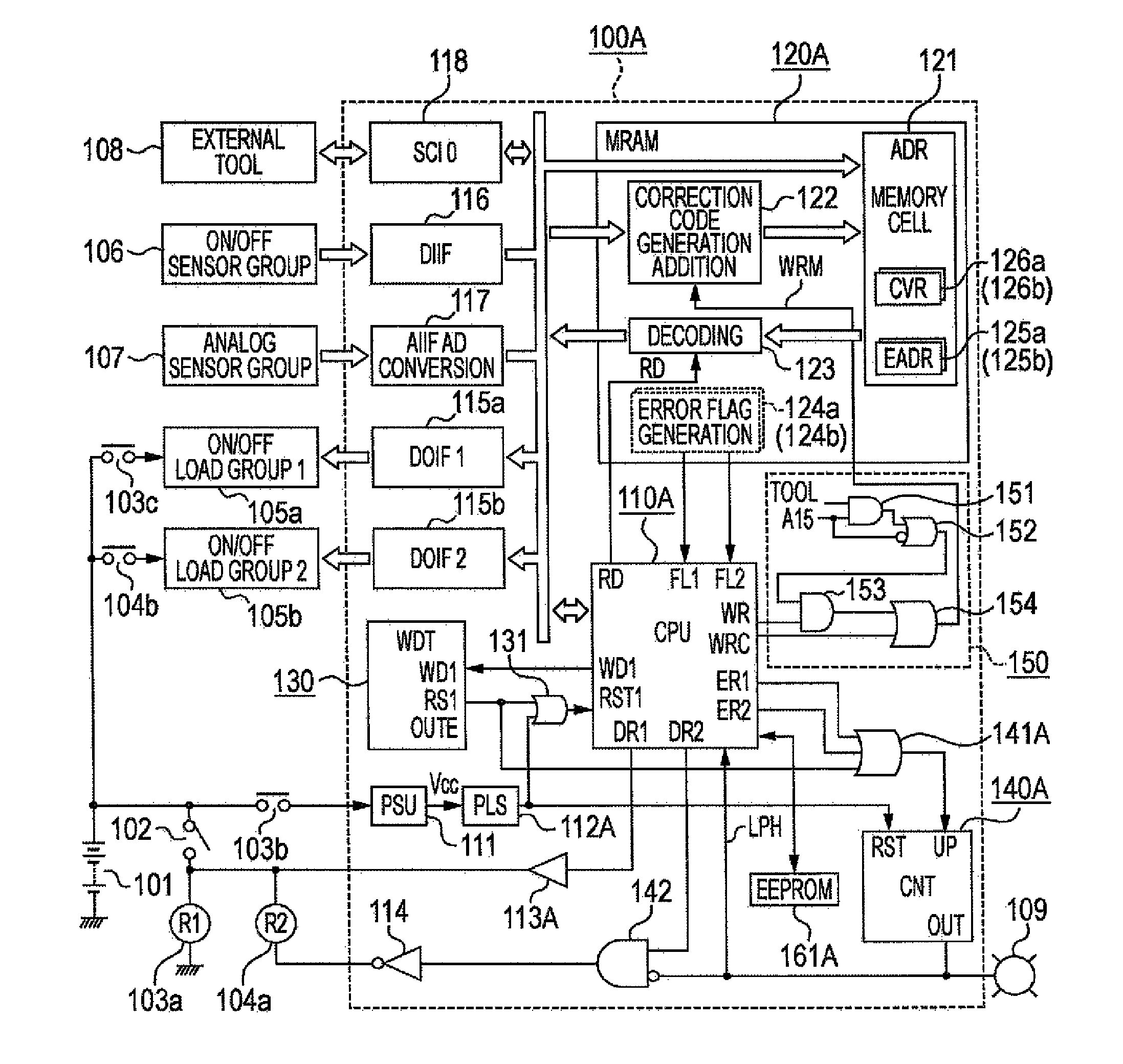
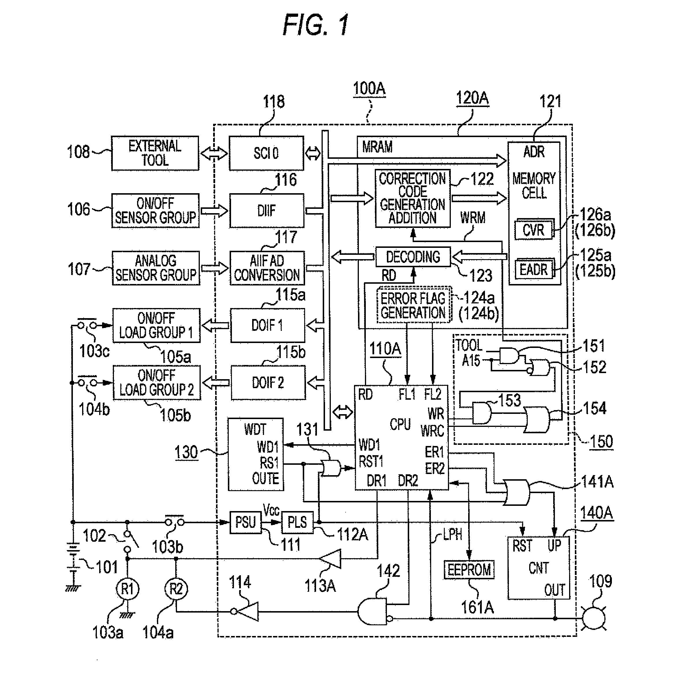
[0046]FIG. 1 showing a circuit block diagram of a first embodiment device of this invention will next be explained.

[0047]In FIG. 1, for example, an electronic controller 100A is a controller of a vehicle mounting engine. An external electric power source 101 as a vehicle mounting battery is connected to the electronic controller 100A through an output contact 103b of an electric power relay. A magnetizing coil 103a of the electric power relay is connected to the external electric power source 101 through an electric power switch 102.

[0048]A positive end of a magnetizing coil 104a of a load electric power relay is connected to the external electric power source 101 through the electric power switch 102. However, a negative end of the magnetizing coil 104a is controlled in electric conduction by an inversion driving circuit element 114 described later.

[0049]Electricity is supplied from a microprocessor 110A described later to a f...

embodiment mode 2

of the Invention

(1) Detailed Explanation of Construction

[0260]FIG. 5 showing a circuit block diagram of a second embodiment device of this invention will be explained with points different from those of FIG. 1 as a center.

[0261]In each figure, common reference numerals show the same or corresponding portions.

[0262]In FIG. 5, an external electric power source 101, an electric power relay and a load electric power relay are arranged in the exterior of an electronic controller 100B. A first electric load group 105a, a second electric load group 105b, an opening-closing sensor group 106, an analog sensor group 107, an external tool 108 and an alarm indicator 109 are connected. Electricity is supplied to the first electric load group 105a from a microprocessor 110B described later through a first output interface circuit 115a so that the first electric load group 105a is operated. Electricity is supplied to the second electric load group 105b through a second output interface circuit 115...

embodiment mode 3

of the Invention

(1) Detailed Explanation of Construction

[0359]FIG. 9 showing a circuit block diagram of a third embodiment device of this invention will be explained with points different from those of FIG. 1 as a center. In each figure, common reference numerals show the same or corresponding portions.

[0360]In FIG. 9, an external electric power source 101, an electric power relay and a load electric power relay are arranged in the exterior of an electronic controller 100C. A first electric load group 105a, a second electric load group 105b, an opening-closing sensor group 106, an analog sensor group 107, an external tool 108 and an alarm indicator 109 are connected. Electricity is supplied to the first electric load group 105a from a microprocessor 110C described later through a first output interface circuit 115a so that the first electric load group 105a is operated. Electricity is supplied to the second electric load group 105b through a second output interface circuit 115b so t...


PUM


Abstract

The invention improves safety of an electronic controller using a nonvolatile memory MRAM able to easily perform reading and writing operations at high speed. Therefore, MRAM for writing a control program from an external tool has a correction code adding writing circuit, a decoding reading-out circuit, and error registers for writing an error generating address number thereto as error data. When the error generating address is designated and confirmation reading-out is performed and an error is generated as before, an overlapping abnormality judgment is made and abnormality notification is performed. A program memory area of MRAM is normally in a writing inhibition state. When the external tool is connected, the inhibition state is released. The error registers are arranged in a data memory area set to no writing inhibition object.

Description

BACKGROUND OF THE INVENTION[0001]1. Field of the Invention[0002]This invention relates to an improvement of an electronic controller having a microprocessor using MRAM (Magnetic Random Access Memory) as a nonvolatile memory able to easily perform reading and writing operations at high speed as a program memory and a data memory.[0003]2. Background Art[0004]In the electronic controller using the microprocessor, it is considered to use MRAM as a nonvolatile memory able to easily perform the reading and writing operations at high speed instead of a former memory construction in which a nonvolatile memory of a mask ROM memory or a flash memory, etc. is set to a program memory, and a battery-backed-up RAM memory is set to a data memory for arithmetic processing.[0005]However, there is a high possibility that stored data are easily changed by a noise error operation, etc. although it is convenient to easily perform the reading and writing operations at high speed. Accordingly, prudent dea...

Claims


Application Information

Patent Timeline
Patent Type & Authority Patents(United States)
IPC IPC(8): G11C29/00G06F21/60G06F21/62G06F21/79
CPCG06F11/1068G11C29/42G11C7/1006G11C2029/0411G11C2029/0401
Inventor HASHIMOTO, KOJINAKAMOTO, KATSUYATSUNEKAZU, SHOSOSUZUKI, SHINSUKE
Owner MITSUBISHI ELECTRIC CORP
Why Eureka
Try Eureka