
Method and system for testing bit failures in array elements of an electronic circuit

a technology of array elements and electronic circuits, applied in the field of hardware emulation and testing, can solve the problem of faster approach than existing solutions, and achieve the effect of improving error detection in real silicon and hard and fast testing

Inactive Publication Date: 2011-08-30
GLOBALFOUNDRIES INC
View PDF3 Cites 2 Cited by
  • Summary
  • Abstract
  • Description
  • Claims
  • Application Information

AI Technical Summary

Benefits of technology

The present invention provides a method and system for reliable and fast testing of memory hardware. The method involves manipulating a representation of memory array hardware, injecting errors into an emulation of the manipulated representation for determining the array's capabilities, and using an emulation computer system for testing the error detection behavior of a wafer tester device. The invention allows for reliable error injection at arbitrary bit positions within the array and improves error detection in real silicon. The technical effects of the invention include faster and more reliable testing of memory hardware and improved error detection.

Problems solved by technology

Therefore, the approach is faster than existing solutions.

Method used


Image

  • Method and system for testing bit failures in array elements of an electronic circuit
  • Method and system for testing bit failures in array elements of an electronic circuit
  • Method and system for testing bit failures in array elements of an electronic circuit

Examples


Embodiment Construction

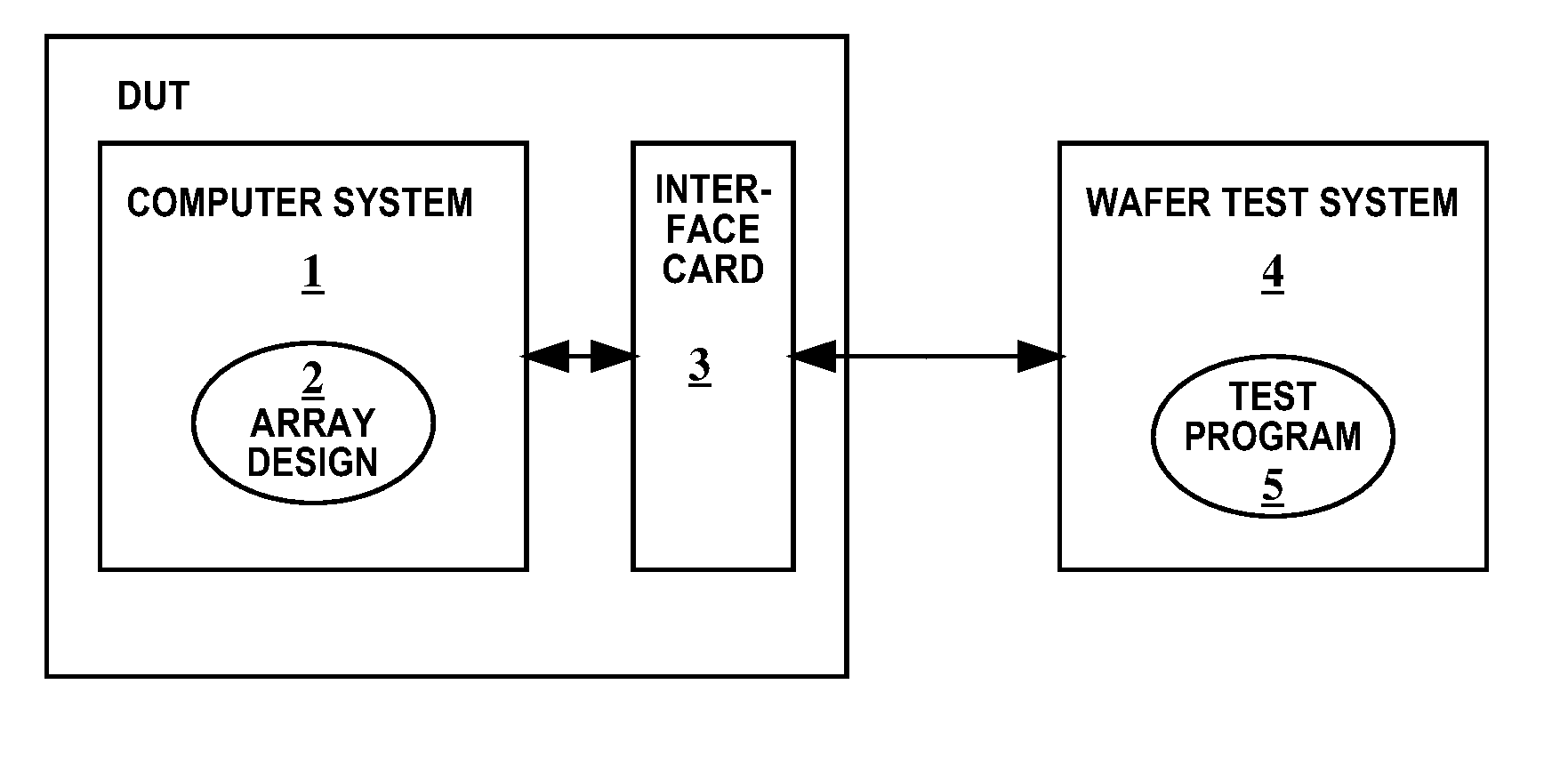
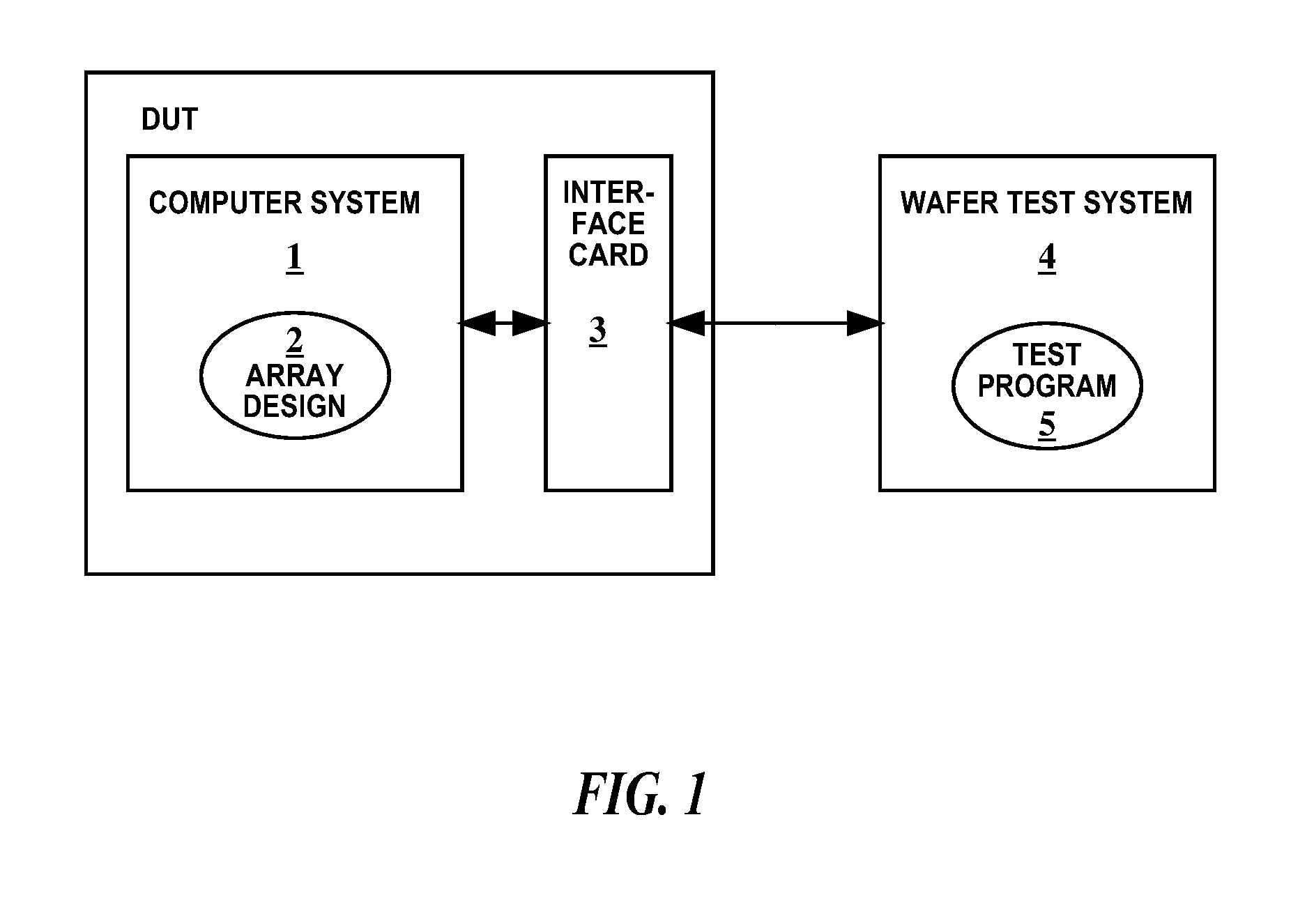
[0023]FIG. 1 shows a block diagram illustrating a test environment for memory arrays according to the invention. Such environment must be prepared using certain methods and operated according to a distinct scheme in distinct order. The invention further requires a certain set of different systems that are connected to each other.

[0024]An emulation computer system 1 executing an especially adapted representation 2 of an array design acts as device under test DUT. Said system 1 is connected via interface card 3 with a wafer test system 4 having a test program 5. The adapted representation 2 of the device under test is executed such that it acts as a virtual test object for the test program 5 that controls the operation of the wafer test system 4. The representation 2 of the design is generated automatically during the model build process. The changes are not generally in the array cells, but in the surrounding read and / or write logic.

[0025]As for executing the complete testing process...


PUM


Abstract

The invention relates to a method and system for testing bit failures in array elements of an electronic circuit. Said method comprising the steps of changing an original hardware representation (DD) of the array such that errors can be injected in a memory by manipulation of associated read and / or write logic of the memory via input signals, building an emulator model (SME) from said changed hardware representation for emulating the array, and injecting errors into the changed hardware representation for determining the array to get stick capabilities.

Description

BACKGROUND OF THE INVENTION[0001]The present invention relates to the field of hardware emulation and testing.[0002]A critical step in the characterization and bringup test of integrated circuits is the test of the array elements or memories they contain. An array element or memory array, in the sense of the present text is, e.g., an L2 cache. It comprises memory cells (the array memory) as well as associated read and write logic to access these cells.[0003]Complex test programs are executed on wafer test systems (testers) in order to check the quality of the arrays. One important function of these test programs is to determine the exact location of failing single-bit memory cells. The process is called Bit Fail Mapping, because maps of bit fails are constructed that provide insight into the weaknesses of the circuit and valuable feedback for circuit design and technology.[0004]Traditionally, developing these test programs for the wafer test systems is extremely difficult because th...

Claims


Application Information

Patent Timeline
Patent Type & Authority Patents(United States)
IPC IPC(8): G06F17/50
CPCG01R31/3171
Inventor KNEISEL, JOACHIMTORREITER, OTTO
Owner GLOBALFOUNDRIES INC
Learn More