Method and device for manufacturing a metal strip by means of continuous casting and rolling

Inactive Publication Date: 2011-09-06
SMS DEMAG AG
View PDF29 Cites 14 Cited by
  • Summary
  • Abstract
  • Description
  • Claims
  • Application Information

AI Technical Summary

Benefits of technology

[0010]The invention is based on the objective of additionally developing a method of the initially cited type and developing a corresponding device that make it possible to increase the flexibility of the method and the device. It should be possible, in particular, to continue the casting process without interruptions if a malfunction occurs or brief maintenance procedures are required in the rolling train or during other interruptions of the rolling process, wherein this ability provides significant economical advantages and advantages with respect to the process control.
[0013]In this case, it is particularly preferred that slabs cast during the continuous operation of the casting machine are removed from the main transport line during a roll exchange in the rolling train and transported back into the main transport line at a later time. This makes it possible to exchange a roll without having to forgo the continuous operation of the casting machine.
[0019]At least one auxiliary storage means, e.g., in the form of a holding pit or a similar device, may be arranged adjacent to the roller table in order to store slabs or preliminary strips. This makes it possible to expand the storage capacity or to realize a prolonged storage time so as to influence the microstructure. This may also be advantageous for metallurgic reasons, namely if prolonged storage times should be realized in the holding pit that acts as a storage means.
[0021]The advantages of the continuous technique, i.e., the continuous operation of the proposed casting and rolling system, in connection with the CSP-technology can be seen in the following characteristics: the structural length of the system is reduced such that the investment costs are lowered. Energy savings can be achieved due to the consequent direct use. In addition, the yield strength is reduced due to the slower rolling speed. It is possible to manufacture products that are difficult to roll and, e.g., very thin (ultrathin) strips (strip thickness approximately 0.8 mm) in large quantities. It is furthermore possible to process special materials (high-strength materials). A combination of wide and thin strips can also be processed. Rolling defects on the strip ends and therefore damages to the rolls can be prevented or at least reduced. The malfunction rate of the system can be reduced and upstrokes can be prevented.

Problems solved by technology

The continuous rolling out of the casting heat has been known for quite some time, but not yet prevailed in the market.
The rigid connection between the continuous casting machine and the rolling train, as well as the march of temperature through the entire system, proved to be difficult to manage.
Both methods—namely the continuous casting and rolling on one hand and the discontinuous casting and rolling on the other hand—are difficult to combine due to the above-described circumstances.

Method used


Image

  • Method and device for manufacturing a metal strip by means of continuous casting and rolling
  • Method and device for manufacturing a metal strip by means of continuous casting and rolling
  • Method and device for manufacturing a metal strip by means of continuous casting and rolling

Examples


Embodiment Construction

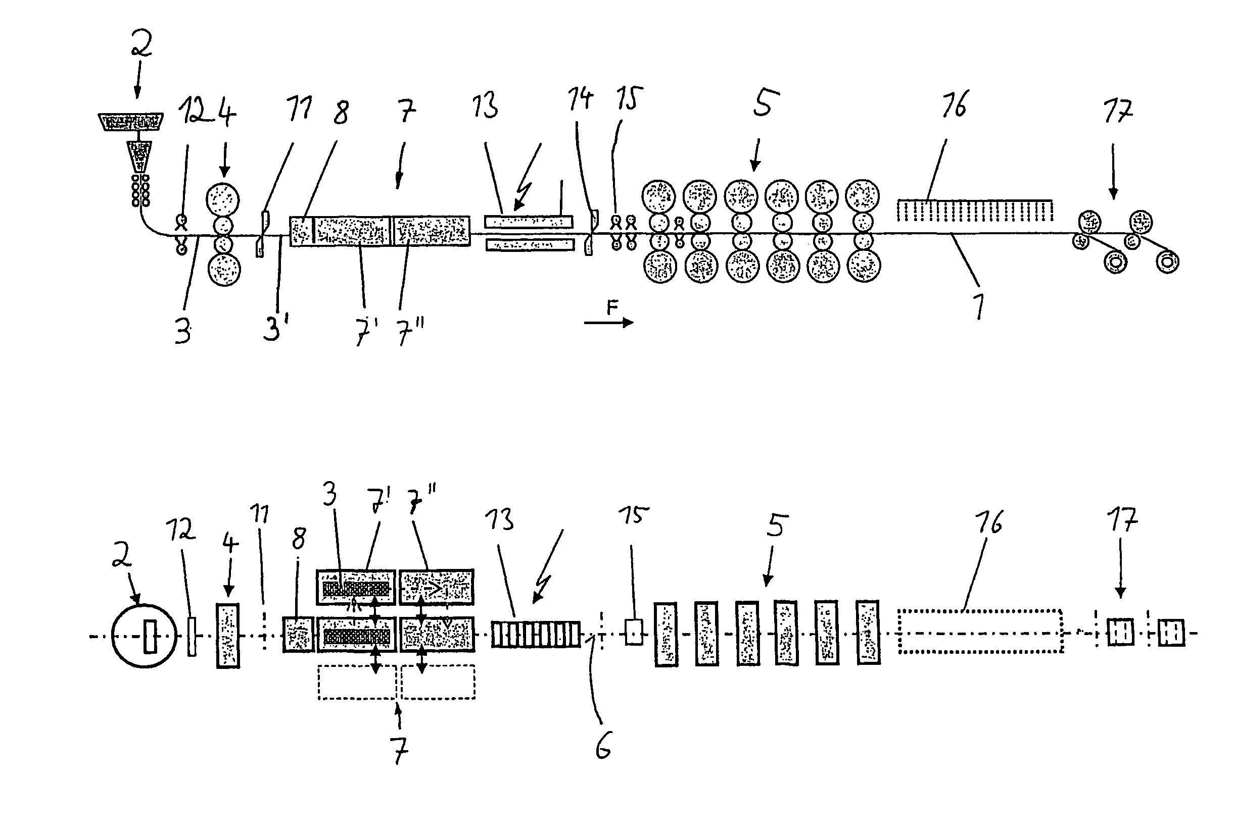
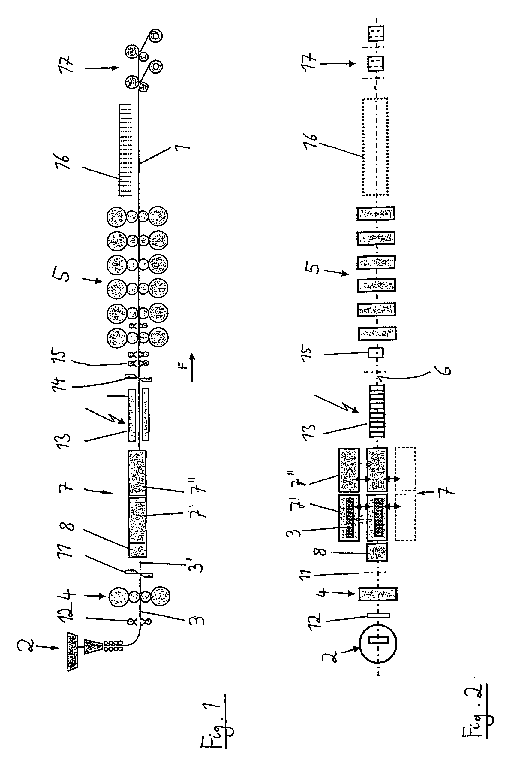
[0034]FIG. 1 and FIG. 2 show a continuous casting and rolling system, in which a metal strip 1 is manufactured. To this end, a thin slab 3 is initially cast in a conventional casting machine 2 and then transported to a rolling train 4, 5 that consists of a roughing train 4 (that features one or more stands) and a finishing train 5. The casting machine 2 features a strand cooling system that is divided into narrow cooling zones in order to realize a temperature zone control over the width of the strip and to thusly adjust a homogenous temperature at the outlet of the continuous casting system.

[0035]The continuous casting and rolling system also features various other elements that are generally known in systems of this type. A descaling sprayer 12 is arranged downstream of the casting machine 2 referred to the strip transport direction F in order to clean the slabs. Strip shears 11 are positioned directly downstream of the roughing train 4. The shears are used for separating the dumm...


PUM

PropertyMeasurementUnit
Transport propertiesaaaaaaaaaa
Heataaaaaaaaaa

Abstract

A method of manufacturing a metal strip includes casting a slab (3) or preliminary strip (3′) in a casting machine (2) and subsequently rolling the cast slab (3) or preliminary strip (3′) in at least one rolling train (4, 5) in a first operating mode with the at least one rolling train being connected with the casting machine for continuously manufacturing the metal strip, and in a second operating mode removing the cast slab (3) or preliminary strip (3′) from the main transport line (6) with a shuttle system arranged between the casting machine (2) and the at least one rolling train (4, 5), storing the removed slab (3) or preliminary strip (3′), and subsequently transporting the removed slab (3) or preliminary strip back into the main transport line, with the removed slab (3) or preliminary strip (3′) being heated to a desired temperature or maintained at a desired temperature prior to the transport back into the main transport line (6) for discontinuously manufacturing the metal strip.

Description

BACKGROUND OF THE INVENTION[0001]1. Field of the Invention[0002]The invention pertains to a method for manufacturing a metal strip by means of continuous casting and rolling, wherein a thin slab is initially cast in a casting machine and this thin slab is subsequently rolled in at least one rolling train by utilizing the primary heat of the casting process, wherein a continuous manufacture of the metal strip (continuous rolling) can be realized in a first operating mode by directly coupling the casting machine to the at least one rolling train, and wherein a discontinuous manufacture of the metal strip (batch rolling) can be realized in a second operating mode by decoupling the casting machine from the at least one rolling train. The invention furthermore pertains to a device for manufacturing a metal strip by means of continuous casting and rolling.[0003]2. Description of the Prior Art[0004]Continuous thin slab / thin strip casting and rolling systems of this type are known as CSP-sy...

Claims


Application Information

Patent Timeline
IPC IPC(8): B22D11/12B21B1/46B22D11/14
CPCB21B1/46B22D11/1206C21D8/0426C21D9/48C21D8/0226B21B39/004Y10T29/49991
Inventor ROSENTHAL, DIETERKRAMER, STEPHANKLEIN, CHRISTOPHSEIDEL, JURGENHACKENBERG, WOLFGANG-DIETMAR
Owner SMS DEMAG AG
Why Eureka
Try Eureka