Vehicular side body structure

a technology of side body and reinforcement member, which is applied in the direction of roofs, transportation and packaging, vehicle arrangements, etc., can solve the problems of difficulty in b>117/b> producing a sufficiently great reactive force for the reinforcing member, and achieve the effect of improving the vehicular side body structure and increasing rigidity

Inactive Publication Date: 2011-09-06
HONDA MOTOR CO LTD
View PDF15 Cites 29 Cited by
  • Summary
  • Abstract
  • Description
  • Claims
  • Application Information

AI Technical Summary

Benefits of technology

[0009]In view of the foregoing prior art problems, it is an object of the present invention to provide an improved vehicular side body structure which employs a reinforcing member formed by extruding an aluminum alloy and thereby has an increased rigidity.
[0010]In order to accomplish the above-mentioned object, the present invention provides an improved vehicular side body structure, which comprises: a side sill including a side sill body formed of a steel plate, and a side sill reinforcing member formed by extruding an aluminum alloy and disposed inside the side sill body; and a reinforcing bracket formed by casting an aluminum alloy, the reinforcing bracket covering the outer surface of the side sill body and fixedly attached to a portion of the outer surface of the steel side sill body, the steel side sill body having a through-hole formed therein, the reinforcing bracket having a protruding portion projecting through the through-hole of the side sill body to be fixed to a corner portion of the side sill reinforcing member, so that the side sill reinforcing member is restrainedly held by the reinforcing bracket.
[0011]Namely, in the present invention, the steel side sill body is covered with the reinforcing bracket that is disposed around the outer surface of the side sill body, formed by casting an aluminum alloy and fixedly attached at a portion to the side sill reinforcing member. Further, the protruding portion is fixed to the corner portion of the side sill reinforcing member via the through-hole formed in the protruding portion of the steel side sill body, so that the side sill reinforcing member is appropriately restrainedly held by the reinforcing bracket. Thus, when a torsional force and / or bending force has acted on the side sill directly or via the center pillar, the torsional force and / or bending force can be transmitted from the reinforcing bracket directly to the side sill reinforcing member; thus, the entire side sill can appropriately receive the torsional force and / or bending force while retaining its sectional shape. In this way, the side sill employing the side sill reinforcing member, formed by extruding an aluminum alloy, and hence the vehicular side body structure can have an increased rigidity against torsion and bending.

Problems solved by technology

However, because the reinforcing member 117 of the generally inverted-S sectional shape tends to easily deform at its individual end portions and thus does not have a (sufficient rigidity against the torsional force, it is difficult for the reinforcing member 117 to produce a sufficiently great reactive force to the torsional force.

Method used


Image

  • Vehicular side body structure
  • Vehicular side body structure
  • Vehicular side body structure

Examples


first embodiment

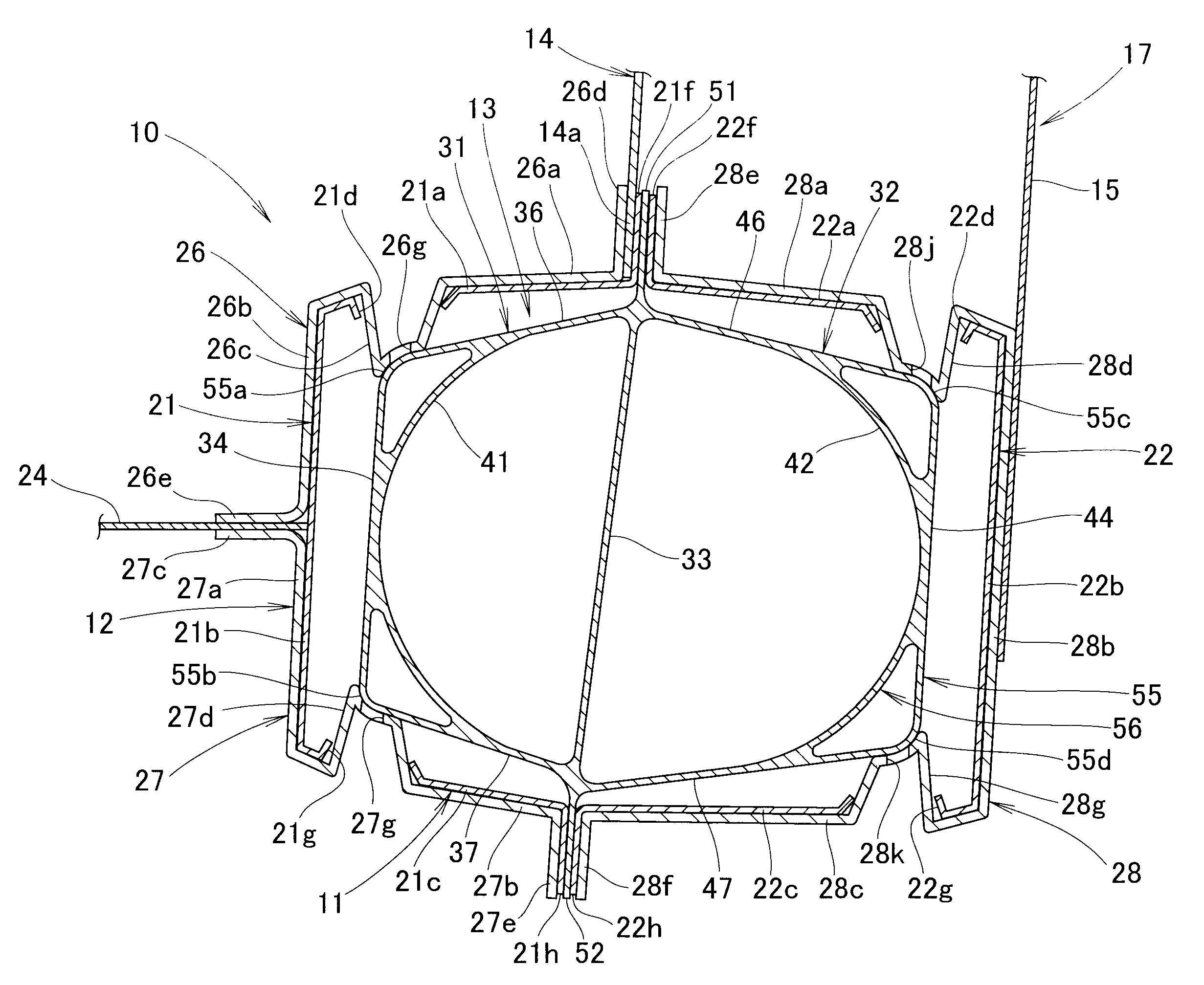
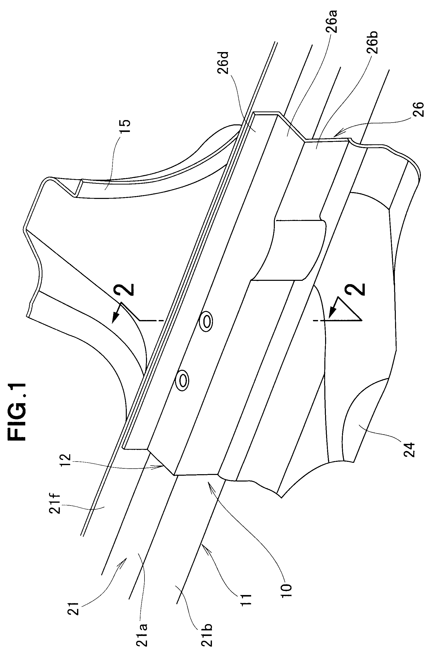
[0030]Reference is now made to FIG. 1 showing in perspective principal sections of a vehicular side body structure according to the present invention; more specifically, FIG. 1 shows a side sill 10 from inside a passenger compartment.

[0031]The side sill 10 comprises a side sill body 11, a reinforcing bracket 12 covering the side sill body 11 to reinforce the side sill body 11, and a side sill reinforcing member (not shown in the FIG. 1) disposed inside the side sill body 11 to reinforce the side sill body 11. Outer center pillar member 15 is fixedly attached to the outer surface of the reinforcing bracket 12 and extends in a vertical direction of the vehicle body.

[0032]Inner center pillar member 14 (not shown in the figure) is disposed inwardly of the outer center pillar member 15, and these outer center pillar member 15 and inner center pillar member 14 together constitute a center pillar 17.

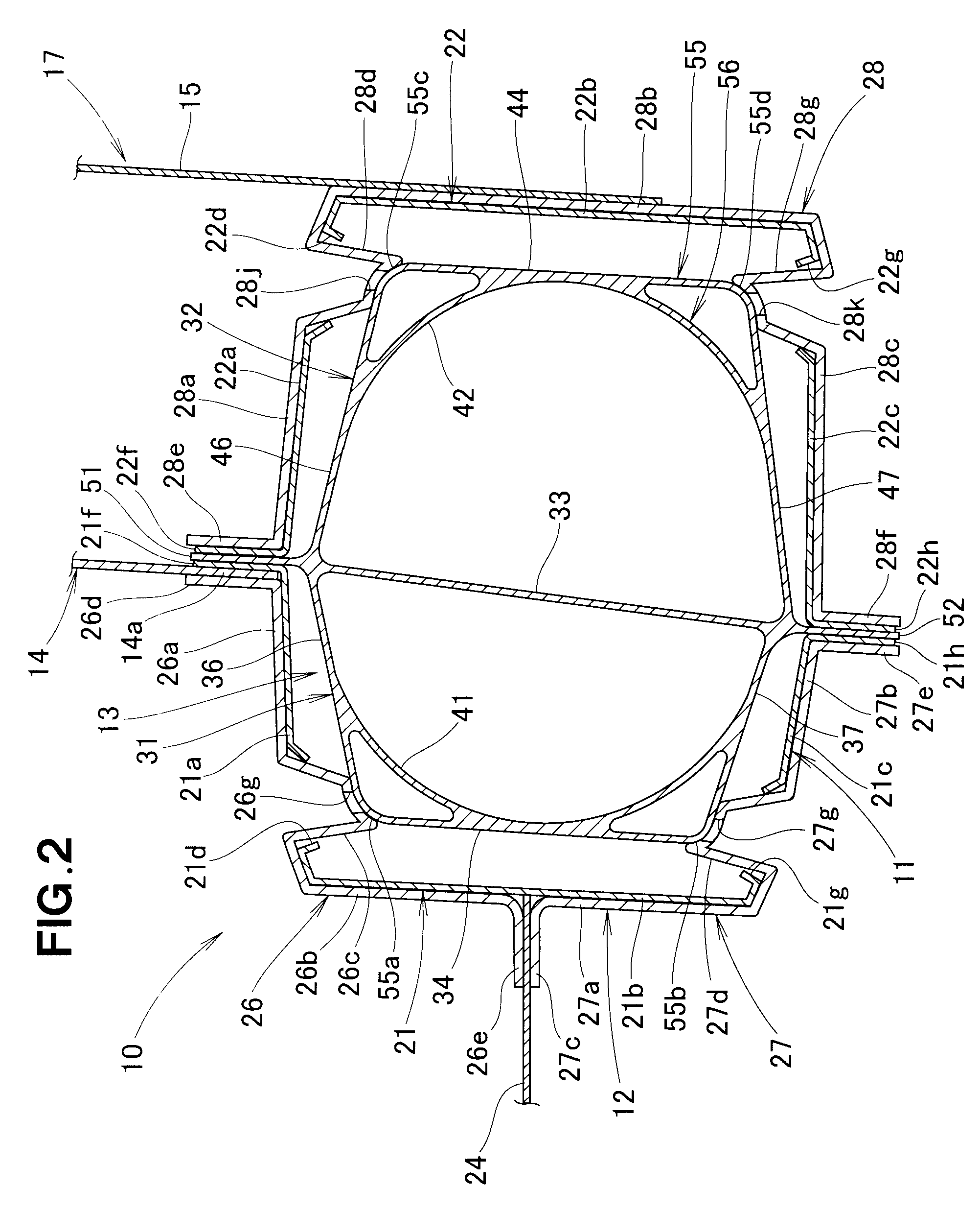
[0033]FIG. 2 is a sectional view taken along the 2-2 line of FIG. 1. As shown in FIG. 2, th...

second embodiment

[0067]The following describe behavior of the vehicular side body structure including the above-described side sill 60, with reference to FIGS. 5A and 5B.

[0068]FIG. 5A shows a state of the side sill 60 before an external force acts on a side surface of the center pillar 17 fixed to the side sill 60. Referring to FIG. 5B, when an external force (torsional force) has acted on the center pillar 17 from the side, the center pillar 17 is deformed to incline as indicated by arrow A, due to which the external force (torsional force) is applied to the inner side sill member. Thus, the side sill body 11 and the reinforcing bracket 12 are both deformed to incline toward the passenger compartment as indicated by arrow B.

[0069]Because the side sill reinforcing member 63 is fixedly joined to the reinforcing bracket 12 at four portions, the side sill reinforcing member 63 inclines together with the reinforcing bracket 12 as the reinforcing bracket 12 inclines; namely, the side sill reinforcing mem...


PUM


Abstract

Side sill includes a side sill body formed of a steel plate, and a side sill reinforcing member formed by extruding an aluminum alloy and provided inside the side sill body. Reinforcing bracket formed by casting an aluminum alloy covers the outer surface of the side sill body. The reinforcing bracket has protruding portions projecting, through through-holes formed in the side sill body, generally toward the interior of the side sill to be fixed to portions of the side sill reinforcing member, so that the side sill reinforcing member is restrainedly held by the reinforcing bracket.

Description

FIELD OF THE INVENTION[0001]The present invention relates generally to vehicular side body structures and more particularly to side sills extending in a front-rear direction of the vehicle body along the opposite side edges of a floor panel.BACKGROUND OF THE INVENTION[0002]In automotive vehicles, side sills are provided to extend along the opposite sides of a floor panel of a passenger compartment in a front-rear direction of the vehicle body, and center and other pillars are fixed at their lower end portions to the side sills. In recent years, there has been developed a vehicular side body structure where a side sill reinforcing member formed by extruding an aluminum alloy is disposed inside a side sill body of a closed cross-sectional shape formed of a steel plate, in order to reduce the overall weight of the side sill and increase the rigidity of the side sill.[0003]FIGS. 7A and 7B hereof are vertical sectional views showing the vehicular side body structure. As shown in FIG. 7A,...

Claims


Application Information

Patent Timeline
Patent Type & Authority Patents(United States)
IPC IPC(8): B60K37/00
CPCB62D25/02B62D25/025B62D25/2036B62D29/002B62D29/008
Inventor YAMADA, TAKAYUKITAKAYAMA, YUSUKE
Owner HONDA MOTOR CO LTD
Why Eureka
Try Eureka