Image display apparatus

a technology of image display and display screen, which is applied in the direction of instruments, television systems, static indicating devices, etc., can solve the problems of wasting time, reducing power consumption, and inability to provide the projection optical system with a zoom function for changing the screen size, etc., so as to reduce reduce power consumption. , the effect of reducing the output of light sources

Inactive Publication Date: 2011-09-06
SEIKO EPSON CORP
View PDF11 Cites 9 Cited by
  • Summary
  • Abstract
  • Description
  • Claims
  • Application Information

AI Technical Summary

Benefits of technology

[0013]An advantage of some aspects of the invention is that it provides an image display apparatus and an image display control apparatus used in the image display apparatus capable of controlling an illumination optical system so as to change a display screen size and decreasing the output of a light source when the display screen size is reduced, thereby reducing power consumption.

Problems solved by technology

Moreover, in the projection TV, it is impractical to provide the projection optical system with a zoom function for changing a screen size.
In addition, news, entertainment programs, or the like are watched for much time and there are many situation that viewers do not watch the programs with interest and just kill time.
Consumption of unnecessary electric power is undesirable in terms of the energy save.
It is also undesirable to consume the unnecessary electric power in the image display apparatus using the fixed focus front projection type projector described above, the direct viewing type liquid crystal TV with a large screen, a plasma TV with large screen, or the like as well as the projection TV.
However, there are the foregoing drawbacks even in the technology disclosed in JP-A-6-138386.

Method used


Image

  • Image display apparatus
  • Image display apparatus
  • Image display apparatus

Examples


first embodiment

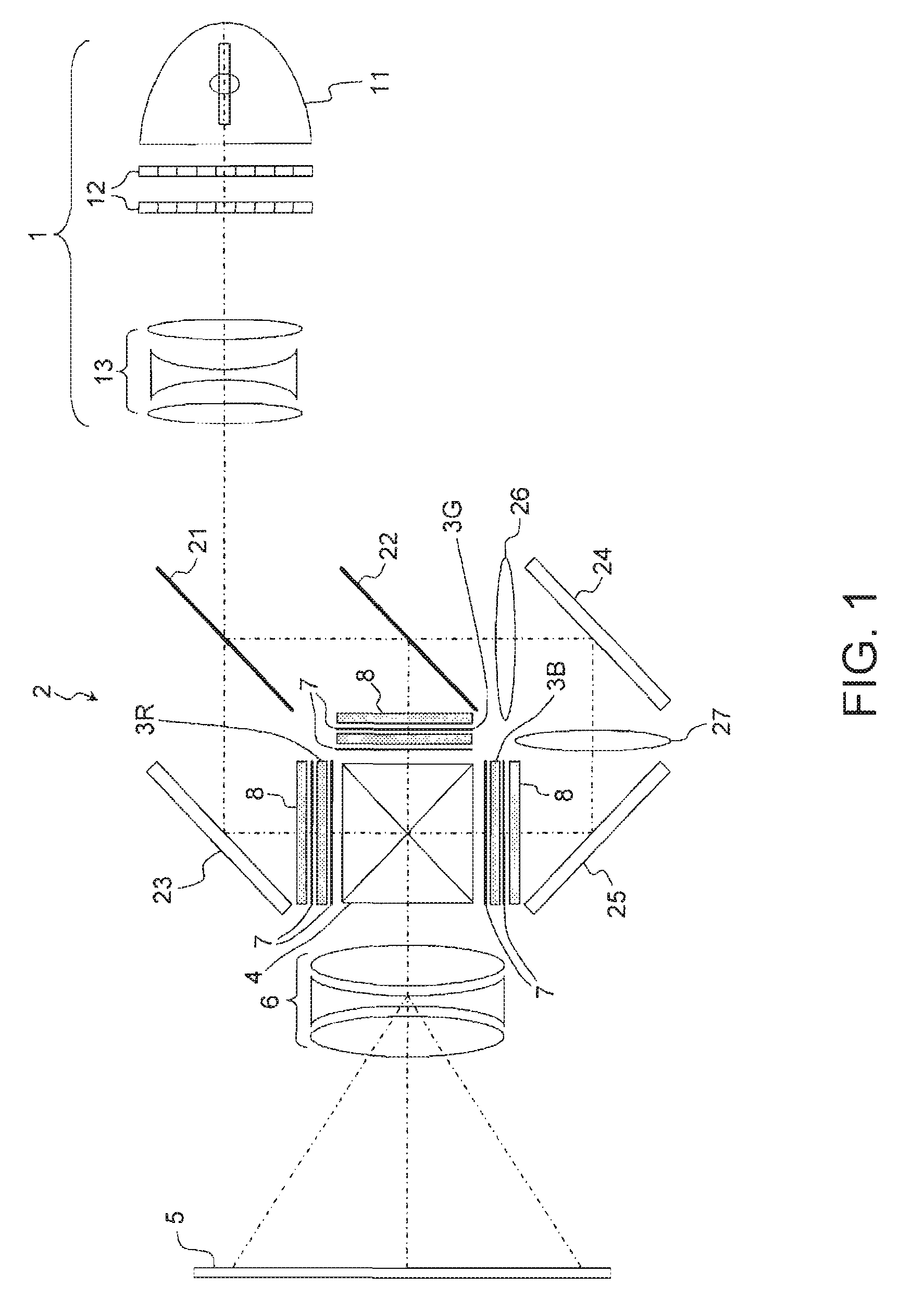
[0067]FIG. 1 is a diagram illustrating a configuration of an optical system in a projector according to the first embodiment. The projector according to the first embodiment is a projector using a 3-plate transmission type liquid crystal panel as a light modulation element, and is a fixed focus type projector used in the projection TV.

[0068]As shown in FIG. 1, the optical system according to the first embodiment includes an illumination optical system 1; a color-separating optical system 2; liquid crystal panels 3R, 3G, and 3B corresponding to 3-color light of R (red), G (green), and B (blue) in the color-separating optical system 2, a cross dichroic prism 4 synthesizing color light modulated by the liquid crystal panels 3R, 3G, and 3B; and a projection optical system (projection lens 6) projecting the light synthesized by the cross dichroic prism 4 onto a display surface 5.

[0069]The illumination optical system 1 includes a light source 11, an integrator lens 12, and a zoom lens 13 ...

second embodiment

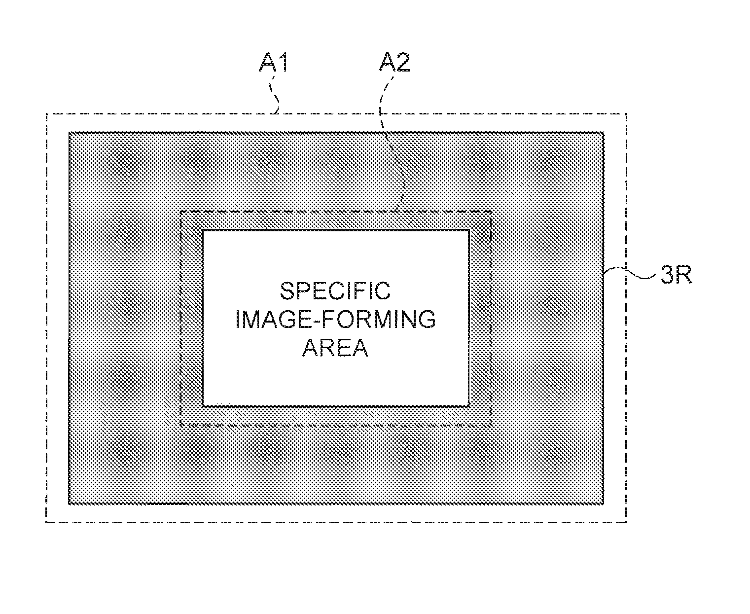
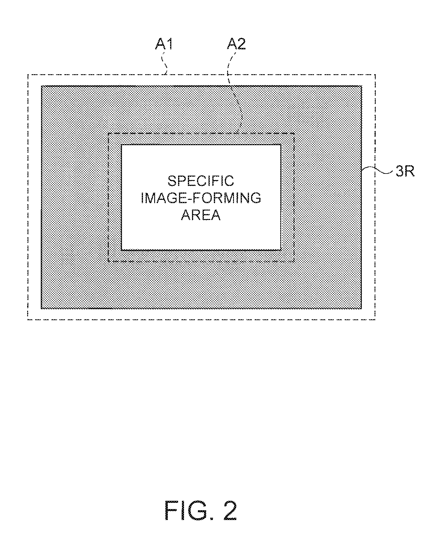
[0095]A projector according to a second embodiment enables the position of a specific image-forming area on an original image-forming area of liquid crystal panels 3R, 3G, and 3B to be changed every predetermined time at the time of illuminating the specific image-forming area onto the original image-forming area of the liquid crystal panels 3R, 3G, and 3B.

[0096]That is, when the screen is configured as a small screen size, only the specific image-forming area is illuminated not the entire original image-forming area of each liquid crystal panel 3R, 3G, and 3B. When the specific image-forming area to be illuminated is always the same position in this manner, degradation of each liquid crystal panel 3R, 3G, and 3B and a deflection plate 7 is not uniform with time lapsed. Consequently, a specific area of the original image-forming area of the liquid crystal panels 3R, 3G, and 3B and the specific area of the deflection plate corresponding to the area can be more rapidly degraded than o...

third embodiment

[0114]As described above, the projector according to the second embodiment can prevent only a specific area of the liquid crystal panels 3R, 3G, and 3B from being degraded more rapidly than the other specific areas by controlling the movement of each liquid crystal panel 3R, 3G, and 3B. However, a projector according to a third embodiment can obtain the same effect by translating in parallel the optical axis of a zoom lens 13 in the illumination optical system 1.

[0115]In addition, when the optical axis of the zoom lens 13 of the illumination optical system 1 is translated in the projector according to the third embodiment, the center of the display of the small screen on the display surface 5 is corrected by translating the optical axis of the projection lens 6.

[0116]FIG. 8 is a diagram illustrating a configuration of the optical system of the projector according to the third embodiment. The optical system of the projector according to the third embodiment includes an illumination o...


PUM

PropertyMeasurementUnit
areaaaaaaaaaaa
screen sizeaaaaaaaaaa

Abstract

An image display apparatus includes a light source; a light modulation element modulating illumination light coming from the light source on the basis of image data; an illumination area modification unit capable of reducing an illumination area for the light modulation element in order to illuminate a specific image-forming area in the image-forming area of the light modulation element; and an image display-processing unit having an illumination area control unit for controlling the illumination area modification unit and a resolution conversion unit for converting a resolution of the image data into a resolution corresponding to the specific image-forming area.

Description

BACKGROUND[0001]1. Technical Field[0002]The present invention relates to an image display apparatus and an image display control apparatus used in the image display apparatus.[0003]2. Related Art[0004]There are known a rear projection type projector configured to project an image on a rear side of a screen using a wide-angle lens or a reflecting mirror and a front projection type projector configured by modifying the arrangement of optical systems being used in the rear projection type projector.[0005]In the rear projection type projector used in an image display apparatus such as a projection television (referred to as the projection TV), a projection optical system is generally designed with the assumption that the distance between a projection lens and the screen is fixed, and the projection lens does not have a zoom function of enlarging or reducing the projection image.[0006]The projection TV generally has a structure in which the optical axis of the projection lens is not perp...

Claims


Application Information

Patent Timeline
Patent Type & Authority Patents(United States)
IPC IPC(8): G09G5/00G02F1/13G02F1/133G03B21/00G09G3/20G09G3/34G09G3/36H04N5/66
CPCG03B21/60
Inventor MIYAZAWA, YASUNAGA
Owner SEIKO EPSON CORP
Why Eureka
Try Eureka