
Planet carrier of a planetary stage with a bogie plate

a technology of planetary stage and bogie plate, which is applied in the direction of machines/engines, final product manufacturing, and gearbox damage, etc., can solve the problems of rotor hubs having direct effects on the gear box, unable to manufacture and the construction of such a planet carrier with a bogie plate is rather a technical challenge, so as to achieve the effect of rapid production

Active Publication Date: 2011-09-13
GAMESA INNOVATION & TECH SA +1
View PDF12 Cites 11 Cited by
  • Summary
  • Abstract
  • Description
  • Claims
  • Application Information

AI Technical Summary

Benefits of technology

An advantage of such a planet carrier according to the invention is that there is no need for any bolts, welding or whatever means to connect the bogie plate to the actual planet carrier, since planet carrier and bogie plate form one piece.
Another advantage of such a planet carrier according to the invention is that the connection between the bogie plate and the actual planet carrier is much stiffer than in the known models of planet carriers with a separate bogie plate.
Still another advantage of a planet carrier according to the present invention is that there is no need for assembly of the bogie plate on the planet carrier, so that the production of the planetary gear stage in which it is used, is faster and the related costs are lower.
An advantage of a planet carrier according to this embodiment is that, once the mold for the casting is made, a very high number of such planet carriers with its bogie plate made is a monolithic piece, can be produced quickly and without much further finishing in a workshop.
Another advantage of casting is that it is a relative cheap process.

Problems solved by technology

If the rotor hub and the input shaft of the gear box were connected rigidly to one another, these deviatory movements would cause damage to the gear box.
However, a disadvantage of these known designs is that the forces and accompanying deformations on the rotor hub have their direct effect on the gear box, since the rotor hub and the input shaft of the gear box are in these designs necessarily rigidly connected to one another.
However the construction of such a planet carrier with a bogie plate is rather a technical challenge.
In particular, the connection of the bogie plate, which holds the shafts supporting the planet wheels, to the planet carrier is critical and very difficult to realize.
A disadvantage of these known planet carriers with a bolted bogie plate is that the assembly of the bogie plate on the planet carrier is complicated, time consuming and requires a lot of high strength materials, which makes the solution rather expensive.
Furthermore, the behavior of the bolted connection between the bogie plate and the planet carrier on the long term is not known.
There is always a risk that bolts get loose after a certain amount of time, so that regular maintenance or inspection of the connection is required.
Another disadvantage of a bolted connection is that the bolted parts always experience a certain, however microscopic small, mutual relative movement when the connection is loaded.
These microscopic movements can cause damage to the parts.
For example in certain circumstances it can cause a typical oxidation of the parts.

Method used


Image

  • Planet carrier of a planetary stage with a bogie plate
  • Planet carrier of a planetary stage with a bogie plate
  • Planet carrier of a planetary stage with a bogie plate

Examples


Embodiment Construction

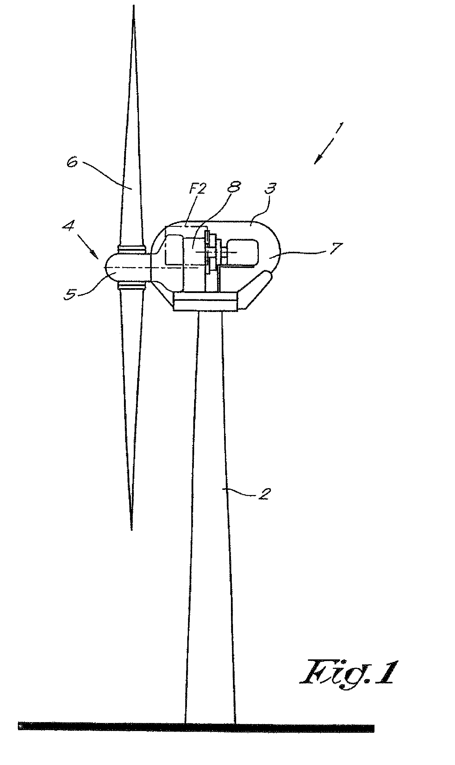
The typical wind turbine 1 represented in FIG. 1 consists of a static supporting structure 2 on which a nacelle 3 is rotatably mounted, which allows for the adjustment of the position of the wind turbine 1 to the wind direction.

In the nacelle 3, a rotor 4 with rotor hub 5 and rotor blades 6 is provided, whereby the rotor 5 is connected to a generator set 7 through a gear unit 8.

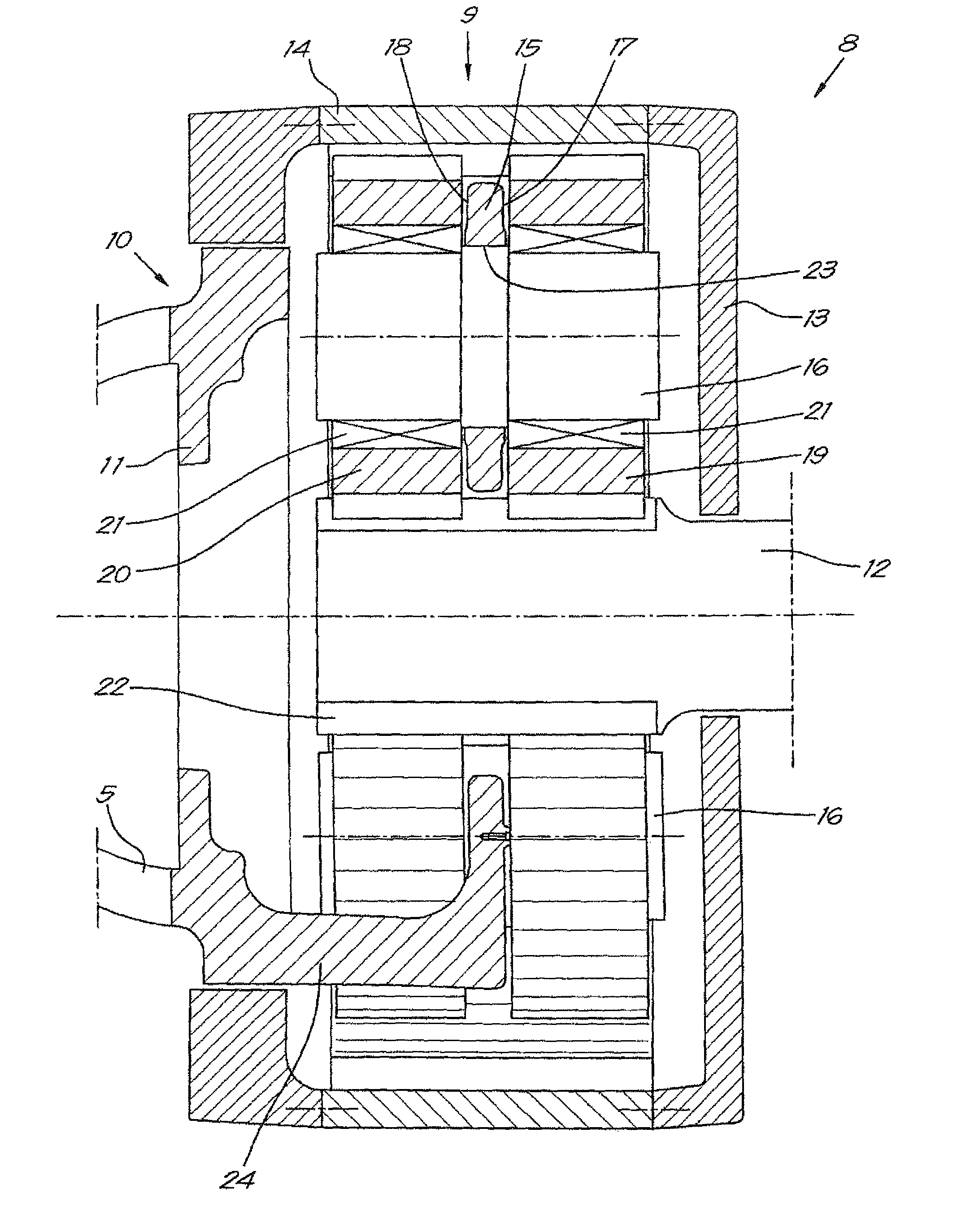
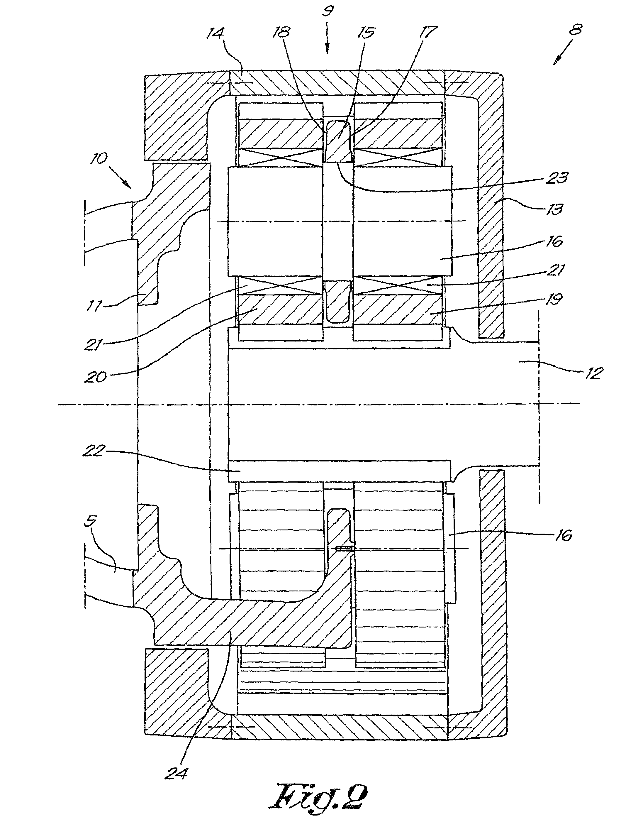
As is represented more in detail in FIG. 2, the gear unit 8 is in this embodiment provided with a planetary gear stage 9.

The input shaft 10 of this planetary gear stage 9, represented in this case by the planet carrier 11 of the planetary gear stage 9, is connected to the rotor hub 5, while the output shaft 12 is connected directly or indirectly through other parts of the gear unit 8 to the generator set 7 (not shown in FIG. 2, but shown in FIG. 1).

The planetary gear stage 9 is mounted in a housing structure 13, which is connected to the nacelle 3 (not shown).

To the housing structure 13 a ring wheel 14 is rig...


PUM


Abstract

A planet carrier of a planetary stage, the planet carrier having a bogie plate, both sides of which planet wheels can be mounted, characterized in that the planet carrier with its bogie plate is made as one monolithic piece.

Description

BACKGROUND OF THE INVENTIONThe present invention relates to a planet carrier of a planetary stage, whereby the planet carrier has a bogie plate, both sides of which planet wheels can be mounted.More specifically, but not exclusively, the present invention relates to a planet carrier of the mentioned type for a wind turbine.DESCRIPTION OF THE RELATED ARTIt is known that in the technology of wind turbines there is a tendency to construct bigger and bigger wind turbines.As a consequence, many attempts are made to reduce the weight of the wind turbines, since the less the weight, the less the forces and tensions on the structure are and therefore the operation costs are dramatically reduced.In the latest versions of wind turbines, lot of effort is put in integrating all the parts of the wind turbine, so that a compacter design is obtained.For example, in old designs the rotor hub of a wind turbine is completely independently supported in the housing by bearings. In that case the rotor h...

Claims


Application Information

Patent Timeline
Patent Type & Authority Patents(United States)
IPC IPC(8): F16H57/08
CPCF03D11/02F16H57/082F05B2260/40311F16H1/48Y02E10/722F16H2001/289F03D15/00F03D15/10Y02E10/72Y02P70/50
Inventor DE UGARTE, PATRIK SEANZETXEBARRIA, JAVIER BARANANOSMOOK, WARREN GREGORYVERBIEST, RIK
Owner GAMESA INNOVATION & TECH SA
Learn More