Composite LED modules

a led module and composite technology, applied in the field of light-emitting diodes, can solve the problems of limited brightness, unsatisfactory use, and complicated white light generation, and achieve the effect of optimizing the use of available space and improving color mixing

Active Publication Date: 2011-09-13
LUMILEDS
View PDF16 Cites 45 Cited by
  • Summary
  • Abstract
  • Description
  • Claims
  • Application Information

AI Technical Summary

Benefits of technology

Hence, according to one aspect of the present invention, a composite, multi-color light emitting diode is provided that comprises a first light emitting diode unit and a second light emitting diode unit. Each light emitting diode unit has an upper surface and a lower surface and is operative to emit light of a first and second wavelength, respectively, through its upper surface. Furthermore, the lower surface of the second light emitting diode unit is arranged on the upper surface of the first light emitting diode unit. In other words, the second diode unit is arranged on top of the first diode unit, and thus occupies a fraction of the light emitting upper surface of the first diode unit. Thereby two diode units are arranged at the space of one diode unit. This is advantageous since it provides for maximally efficient use of the available space and for better color mixing.
However, according to one embodiment, the upper surface of the first light emitting diode unit and the lower surface of the second light emitting diode unit each comprise an electrode that are electrically interconnected. Thereby the first and second units are connected in series without use of a separate interconnecting circuit or bond wire. In effect, the number of bond wires are limited resulting in easer manufacturing and an increased light-emitting surface (since the bond wire would otherwise occupy parts of the LED light path). Specific modification could be made in the plating layers of conventional light emitting diodes in order to enhance their electrical and thermal performance. One part of this additional plating layout could be used to attach the second diode unit on the first diode unit, and another, electrically interconnected part could receive a bond wire for simultaneous driving an upper electrode of the first diode and a lower electrode of the second diode.
The present invention is advantageous compared to conventional LED arrangements in that it provides compact and powerful LED modules with a high degree of color mixing. For example, the present invention can provide compact and highly powerful white LED modules, by combining e.g. a blue LED unit and a yellow LED unit. Thereby the light emitting devices in accordance with the present invention can be advantageously used for general lighting purposes.
Any type of LED units could be used to build a composite LED module in accordance with the present invention. The thin types of LED units are preferably modified to enhance their electrical and thermal performance. For example, additional metal plating can be added to the top surface in order to facilitate conventional attachment of another LED unit thereto. It is also possible to add plating structures for electrical interconnection of the attached LED unit (like bond wire pads).

Problems solved by technology

This characteristic is useful for many applications, but complicates the generation of white light since it by definition is constituted by a mixture of wavelengths.
However, such white LEDs have limited brightness and are thus not satisfactory for use in applications requiring high light output levels.
However, the luminance of a single LED is limited.
For general lighting purposes, a large number of LEDs have to be put together, which makes the illumination device bulky.
This bulkiness is a general problem for compact applications, and typically also gives rise to problems in the color appearance of the device since it makes homogenous color mixing more complicated.

Method used


Image

  • Composite LED modules
  • Composite LED modules
  • Composite LED modules

Examples


Embodiment Construction

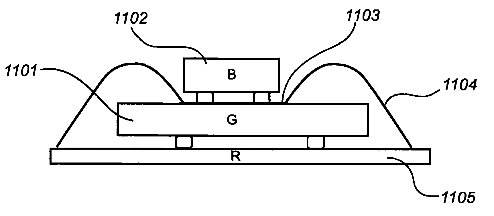
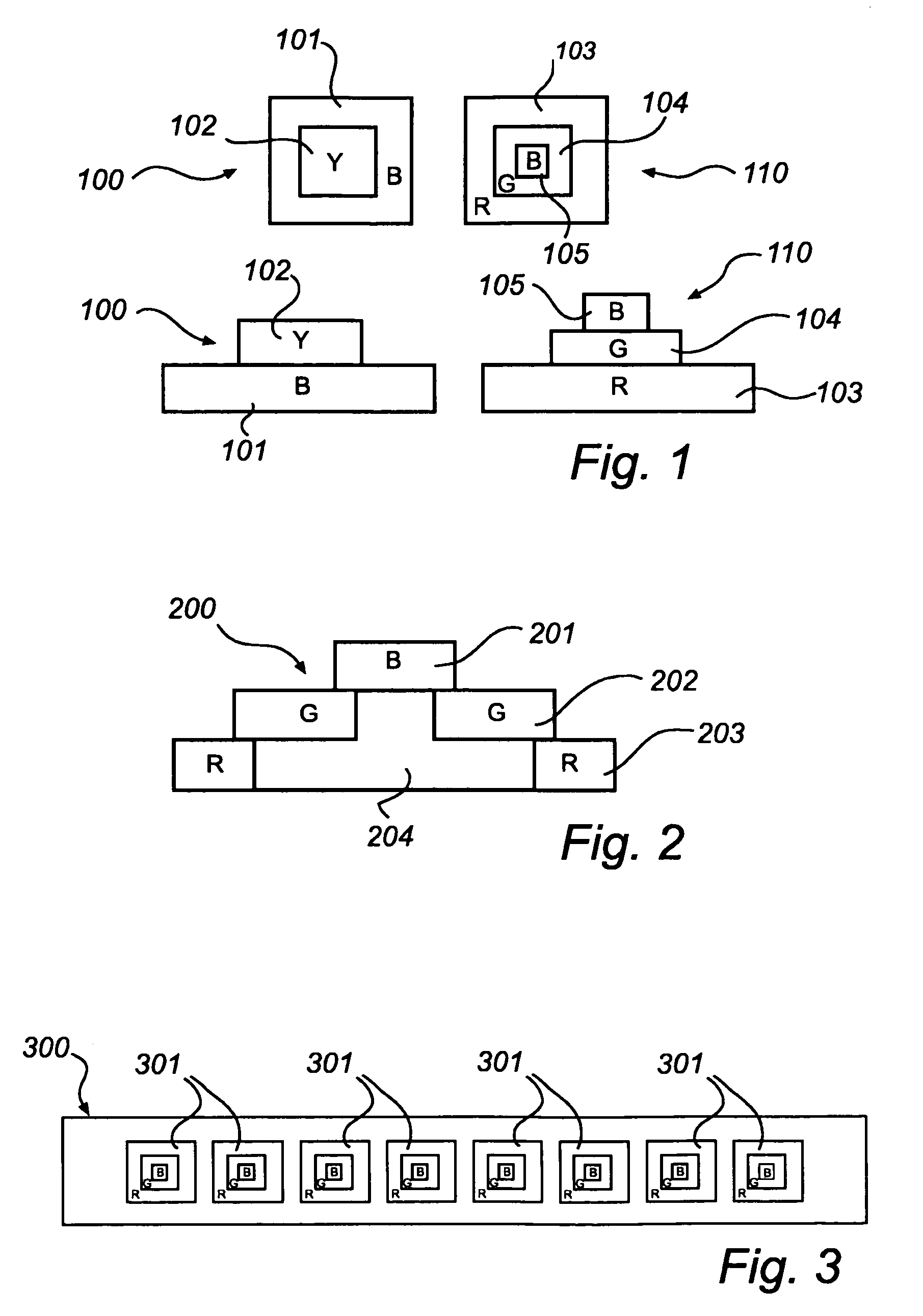
FIG. 1 illustrates two alternative composite LEDs, 100 being a two color blue 101 and yellow 102 composite LED and 110 being a three color red 103, green 104, and blue 105 composite LED.

In an alternative embodiment, as illustrated in FIG. 2, a composite LED 200 is provided with a heat sink 204 on which the LED units 201, 202, 203 are arranged. The heat sink 204 serves to remove heat from the LED units during operation.

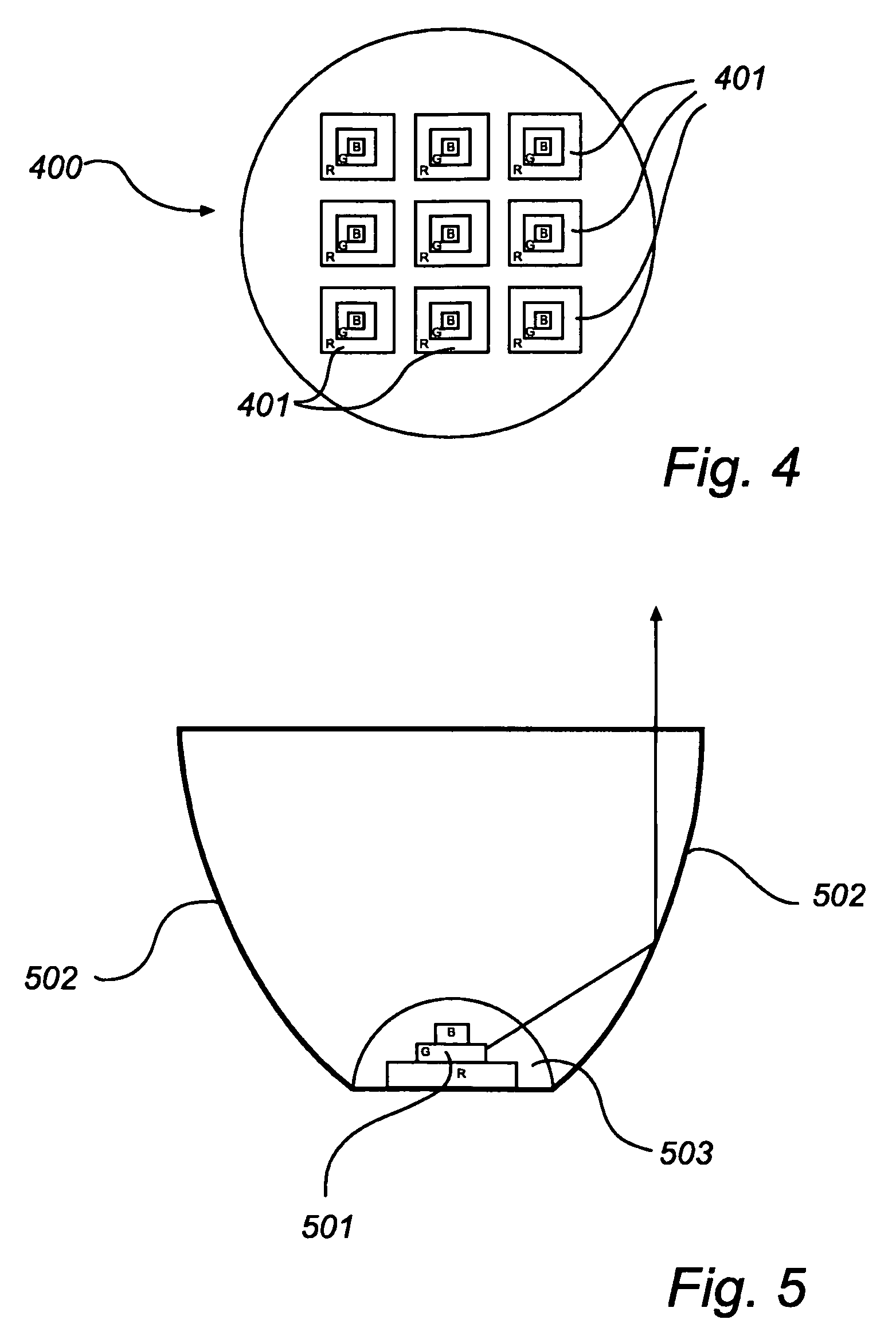
The composite LED is advantageous for use in many applications. For example, as illustrated in FIG. 3, an 8-by-1 array of composite LEDs can be arranged in line lamp 300. An alternative configuration in the form of a spot lamp 400 is illustrated in FIG. 4, carrying a 3-by-3 array of composite LEDs 401.

According to one embodiment, as illustrated in FIG. 5, a composite LED 501 can be arranged with a reflector 502. In such an arrangement, the composite LED may furthermore be encapsulated in an encapsulating material 503. The reflector can, for example, be formed out of al...


PUM

PropertyMeasurementUnit
first wavelengthaaaaaaaaaa
second wavelengthaaaaaaaaaa
wavelengthaaaaaaaaaa

Abstract

A composite multi-color light emitting diode device includes a first light emitting diode unit and a second light emitting diode unit that is arranged on top of the first light emitting diode unit for emitting two different wavelengths of electromagnetic radiation. A third light emitting diode unit may be arranged on top of the second light emitting diode unit, thereby providing a stack of three light emitting diode units. Alternatively, the third light emitting diode unit may be arranged on the first light emitting diode unit, thereby providing two light emitting diode units side-by-side on top of the first light emitting diode unit.

Description

TECHNICAL FIELD OF THE INVENTIONThe present invention relates to Light Emitting Diodes (LEDs).TECHNOLOGICAL BACKGROUNDLED modules for general lighting (LED lamps, LED luminaries etc.) are conventionally made of a single LED, or a system of LEDs that are arranged in two dimensions.An LED is characterized by its ability to generate monochrome light at a well-defined wavelength. This characteristic is useful for many applications, but complicates the generation of white light since it by definition is constituted by a mixture of wavelengths. One way to solve this problem is to add a wavelength converting material to an LED. For example, blue LEDs have been coated with a wavelength converting material that converts some of the blue light to yellow light. Thereby a white light can be provided as a mixture of converted yellow light and unconverted blue light. However, such white LEDs have limited brightness and are thus not satisfactory for use in applications requiring high light output ...

Claims


Application Information

Patent Timeline
Patent Type & Authority Patents(United States)
IPC IPC(8): H01L29/20H01L33/20H01L33/58H01L33/60
CPCH01L25/0756H01L33/20H01L33/58H01L33/60H01L2224/73265H01L2224/48091H01L2924/00014
Inventor WANG, LINGLIVAN OS, KOENANSEMS, JOHANNES PETRUS MARIA
Owner LUMILEDS
Why Eureka
Try Eureka