
Power factor correction by measurement and removal of overtones

a technology of power factor and overtone, applied in the direction of pulse manipulation, pulse technique, instruments, etc., to achieve the effect of reducing the cost of manufacturing and testing operating devices, reducing the sensitivity to operating voltage and current variability, and increasing the flexibility of designing devices

Inactive Publication Date: 2011-09-13
WRATHALL ROBERT
View PDF16 Cites 7 Cited by
  • Summary
  • Abstract
  • Description
  • Claims
  • Application Information

AI Technical Summary

Benefits of technology

The solution achieves nearly sinusoidal rectified load current waveforms, significantly improving power factor efficiency, reducing sensitivity to voltage and current variability, and lowering manufacturing and testing costs by making both overtone and phase-shifted power factors very close to one.

Problems solved by technology

The input supply signal is at an input supply current susceptible of having at least one overtone of the fundamental supply frequency.

Method used


Image

  • Power factor correction by measurement and removal of overtones
  • Power factor correction by measurement and removal of overtones
  • Power factor correction by measurement and removal of overtones

Examples


Embodiment Construction

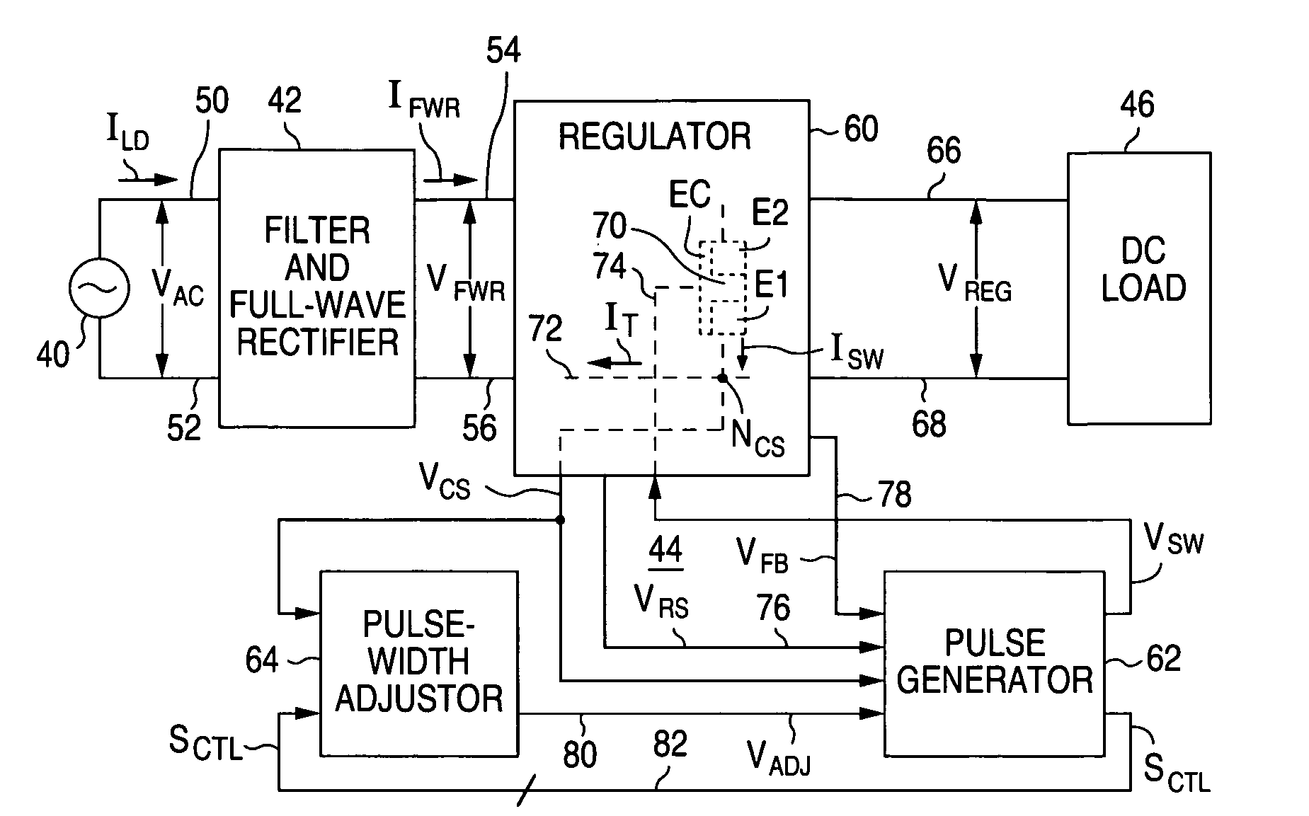
[0048]Referring to FIG. 9, it illustrates a power-supply circuit having which contains power factor correction circuitry configured in accordance with the invention for making overtone power factor PFOvertone and phase-shifted power factor PFPhase simultaneously very close to one. The power-supply circuit in FIG. 9 is formed with an AC power supply 40, a filter and full-wave rectifying circuit 42, regulator / control circuitry 44, and a DC load 46. AC power supply 40 is typically at the location of a power company. Components 42, 44, and 46 are typically at the location of a power consumer. The combination of filter and full-wave rectifier 42 and regulator / control circuitry 44 form a power factor correction circuit.

[0049]AC power supply 40 furnishes analog input AC supply voltage signal VAC at fundamental power supply frequency fAC, typically 60 Hz. AC supply voltage VAC, which varies substantially sinusoidally with time according to Eq. 1, is provided between a pair of main electrica...


PUM


Abstract

A power factor correction circuit (42 / 44) responsive to an input power supply signal at an input supply voltage (VAC) that varies largely sinusoidally with time at a fundamental supply frequency contains regulator / control circuitry (60, 62, and 64) for measuring and removing overtones (ILDm or IFWRm) in the input supply current (ILD) or in a rectified form (IFWR) of the input supply current. Each overtone is expressible as the product of an amplitude component (Im) and a sinusoidal function (Im sin [(m+1)ωACt]) that varies with time at an integer multiple of the fundamental supply frequency. The regulator / control circuitry measures an overtone by determining the overtone's amplitude component. After generating an adjustment factor (SADJ) largely as the product of that overtone's amplitude component and an associated sinusoidal function, the regulator / control circuitry adjusts the input supply current or its rectified form by an amount corresponding to the adjustment factor for each measured overtone.

Description

CROSS-REFERENCE TO RELATED APPLICATION[0001]This is a division of U.S. patent application Ser. No. 11 / 784,423, filed 6 Apr. 2007, now U.S. Pat. No. 7,719,862 B2.FIELD OF USE[0002]This relates to power factor correction.BACKGROUND[0003]Power companies furnish alternating-current (“AC”) power in the form of supply voltages that vary largely sinusoidally with time. Referring to FIG. 1, it illustrates a simplified version of a power-supply circuit in which AC power supply 20, such as that of a power company, provides analog input AC supply voltage VAC at fundamental power supply frequency fAC to load 22 at a consumer's location. AC supply voltage fAC is specifically given as:VAC=V0 sin(ωACt)  (1)where V0 is a voltage amplitude component, ωAC is the fundamental angular supply frequency equal to 2πfAC, and t is time. Load current ILD flows through load 22, causing it to consume instantaneous power PI equal to ILDVAC.[0004]The time variation of load current ILD depends on the constituency ...

Claims


Application Information

Patent Timeline
Patent Type & Authority Patents(United States)
IPC IPC(8): H02M1/12G01R23/20H03K5/08
CPCG05F1/70Y02P80/10
Inventor WRATHALL, ROBERT S.
Owner WRATHALL ROBERT
Learn More