Separation method and apparatus

a technology of gaseous mixture and separation method, which is applied in the direction of lighting and heating apparatus, refrigeration machines, solidification, etc., can solve the problems of excessive vaporization of liquids within the distillation column, and the unforeseen effect of vaporization

Active Publication Date: 2011-09-20
PRAXAIR TECH INC
View PDF11 Cites 22 Cited by
  • Summary
  • Abstract
  • Description
  • Claims
  • Application Information

AI Technical Summary

Benefits of technology

[0018]A crude liquid oxygen stream formed from the oxygen containing column bottoms of the higher pressure columns can be valve expanded and introduced into the lower pressure column for rectification without being subjected to indirect heat exchange to further cool the crude liquid oxygen stream prior to its being valve expanded.

Problems solved by technology

For instance, if the flow to the turboexpander is warmer than expected, the exhaust temperature may be higher than expected so as to cause unforeseen and excessive vaporization of liquids within the distillation columns.

Method used


Image

  • Separation method and apparatus
  • Separation method and apparatus
  • Separation method and apparatus

Examples


Embodiment Construction

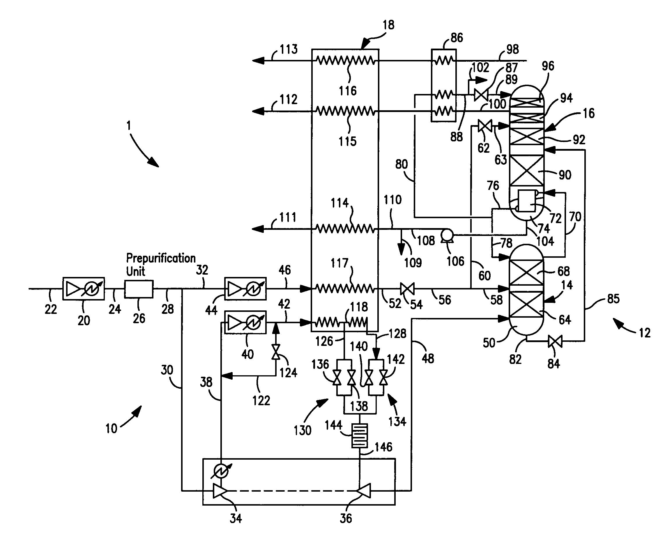
[0039]With reference to FIG. 1, an air separation plant 1 is illustrated for exemplary purposes. As indicated above, the present invention in its more broader aspects has equal application to other separation process, for example, those involving natural gas.

[0040]Air separation plant 1 includes a compression system 10 to compress the air to pressures suitable for its rectification within an air separation unit 12 having a higher pressure column 14 and a lower pressure column 16. Rectification of the air separates the components of the air into oxygen-rich and nitrogen-rich fractions that are extracted as oxygen-rich and nitrogen-rich streams that are introduced into a main heat exchanger 18 to indirectly exchange heat from the compressed air to the oxygen-rich and nitrogen-rich streams and thereby to cool the compressed air to a temperature suitable for the rectification thereof. As would occur to those skilled in the art, in other separation processes, a feed such as natural gas m...


PUM


Abstract

Separation method and apparatus for separating a gaseous mixture, for example, air, in a cryogenic rectification plant in which a compressed stream is divided into subsidiary streams that are extracted from a main heat exchanger of the plant at higher and lower temperatures. The two streams are then combined and expanded in a turboexpander to generate refrigeration for the plant. The flow rates of the two streams are adjusted to control inlet temperature of a turboexpander supplying plant refrigeration and to minimize potential deviation of the turboexpander exhaust from a saturated vapor state. Control of the expansion ratio can advantageously be applied to allow variable liquid production from the rectification plant.

Description

FIELD OF THE INVENTION[0001]The present invention relates to a method and apparatus for separating a gaseous mixture in a cryogenic rectification plant in which the temperature of a compressed stream of the gaseous mixture fed to a turboexpander and used to supply refrigeration to the plant is controlled by removing two streams of the compressed stream from the plant main heat exchanger, controlling the flow rates of the two streams and then combining the two streams prior to their introduction into the turboexpander.BACKGROUND OF THE INVENTION[0002]It has long been known to separate a variety of gaseous mixtures by cryogenic rectification, for example pretreated air and natural gas. In such processes, the gaseous mixture to be separated is pressurized, purified and then cooled to a temperature suitable for its rectification. The rectification of the gaseous mixture occurs within one or more distillation columns. Each of the columns has mass transfer elements such as trays or packin...

Claims


Application Information

Patent Timeline
Patent Type & Authority Patents(United States)
IPC IPC(8): F25J3/00
CPCF25J3/04024F25J3/0423F25J3/0429F25J3/04296F25J3/04303F25J3/04345F25J3/04412F25J3/04781F25J3/04787F25J3/04812F25J5/002F25J3/0409Y10S62/901F25J2210/04F25J2240/42F25J2245/40F25J2290/42Y10S62/903F25J3/02F25J3/04
Inventor HOWARD, HENRY EDWARDJIBB, RICHARD JOHN
Owner PRAXAIR TECH INC
Why Eureka
Try Eureka