Track-switching device and method

a track-switching device and track technology, applied in the field of vehicles' tracks, can solve the problems of limiting the utility of the aforementioned one-sided track switch, lag or delay in the track-switch to take place, and response time that may not meet the desired response tim

Active Publication Date: 2011-09-20
UNIVERSAL CITY STUDIOS LLC
View PDF25 Cites 4 Cited by
  • Summary
  • Abstract
  • Description
  • Claims
  • Application Information

AI Technical Summary

Problems solved by technology

However, in rides that have multiple tracks and require vehicles to switch tracks, there exists a lag or delay for the track-switch to take place.
However, known track-switching devices such as those mentioned above typically require a response time that may not meet the desired response time in some applications, such as amusement park settings, and are restricted to rail applications where the principal wheel assembly rides on a single side of the track, and lateral guidance is provided by a flange on the wheel.
These features substantially limit the utility of the aforementioned one-sided track switch assemblies
As such, the inertia of the drive mechanism and the switch assembly is always coupled to the mechanical system, providing practical limits to the combined acceleration and positioning accuracy of said switch types.
Manufactures have increasingly employed more powerful primary drive devices for switches that yield diminishing returns, as the self-inertia of larger and larger (e.g., electric) motors presents a first-order effect that defines the torque / horsepower / speed rise-time curve, particularly when the physical size and packaging of such devices is considered, this last resulting in necessarily causing such devices to be remote from the switched device, further increasing inertia and attendant switch timing delay.
Accordingly, to date, no suitable apparatus or method for rapid track-switching is available.

Method used


Image

  • Track-switching device and method
  • Track-switching device and method
  • Track-switching device and method

Examples


Embodiment Construction

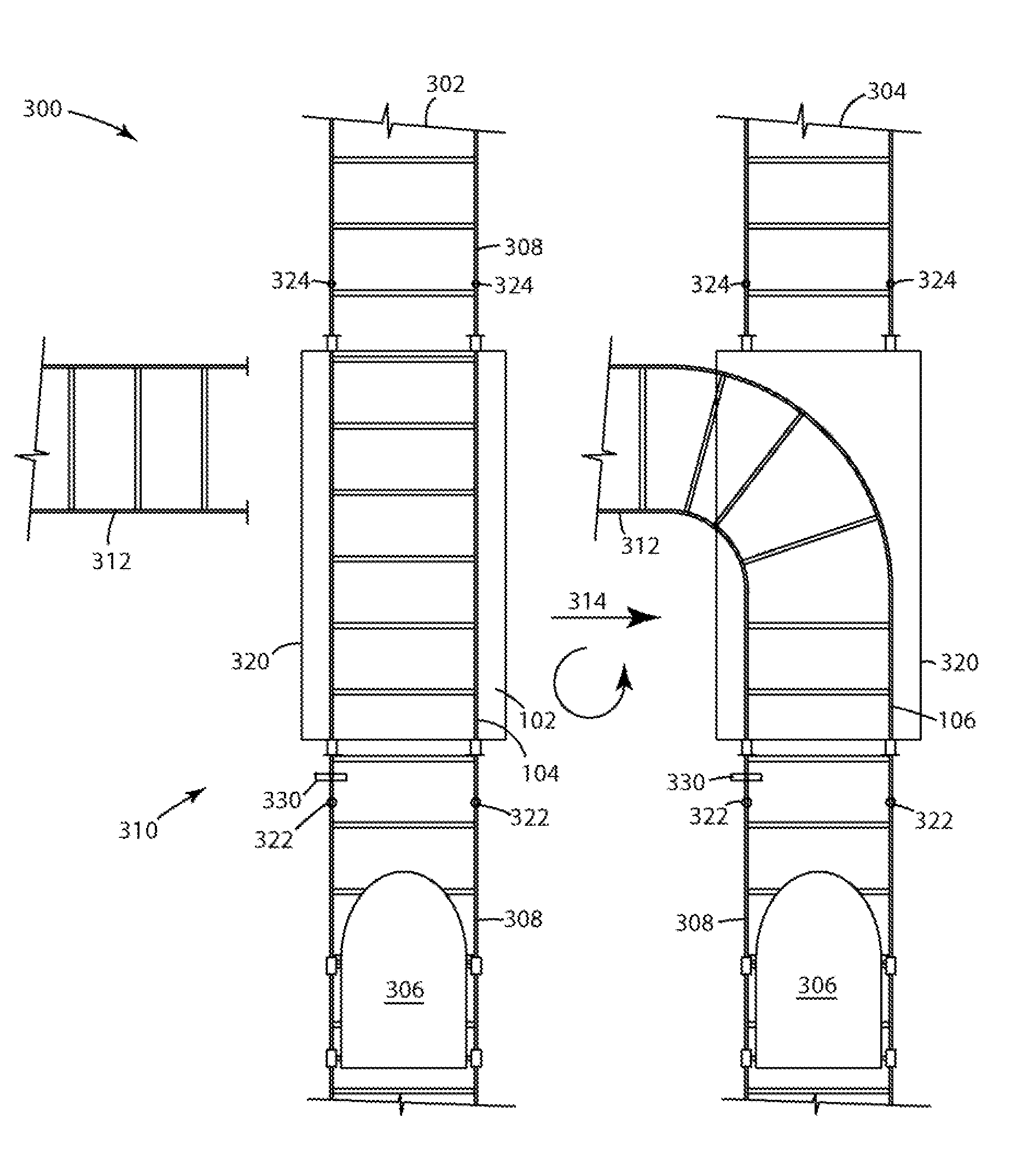
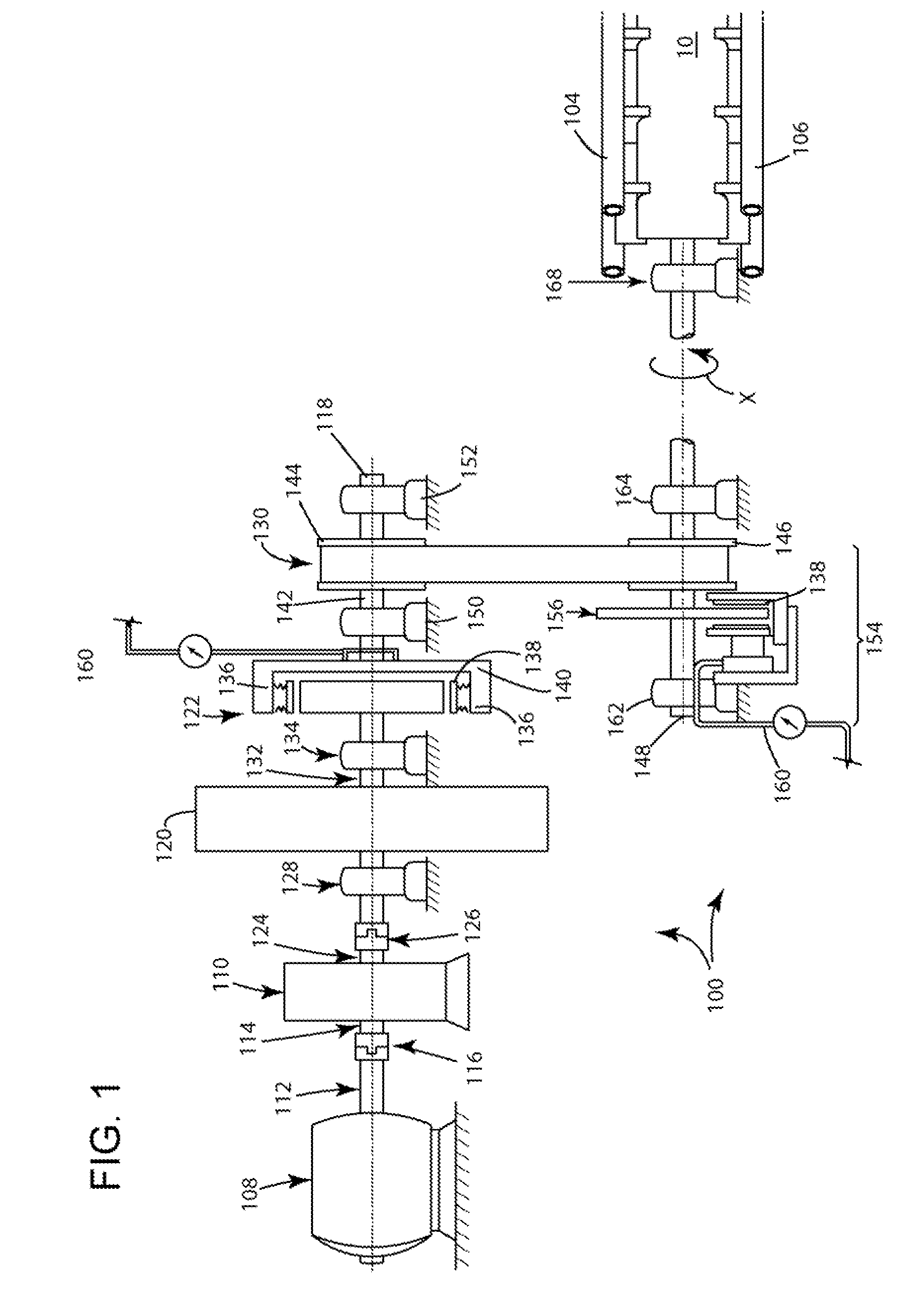
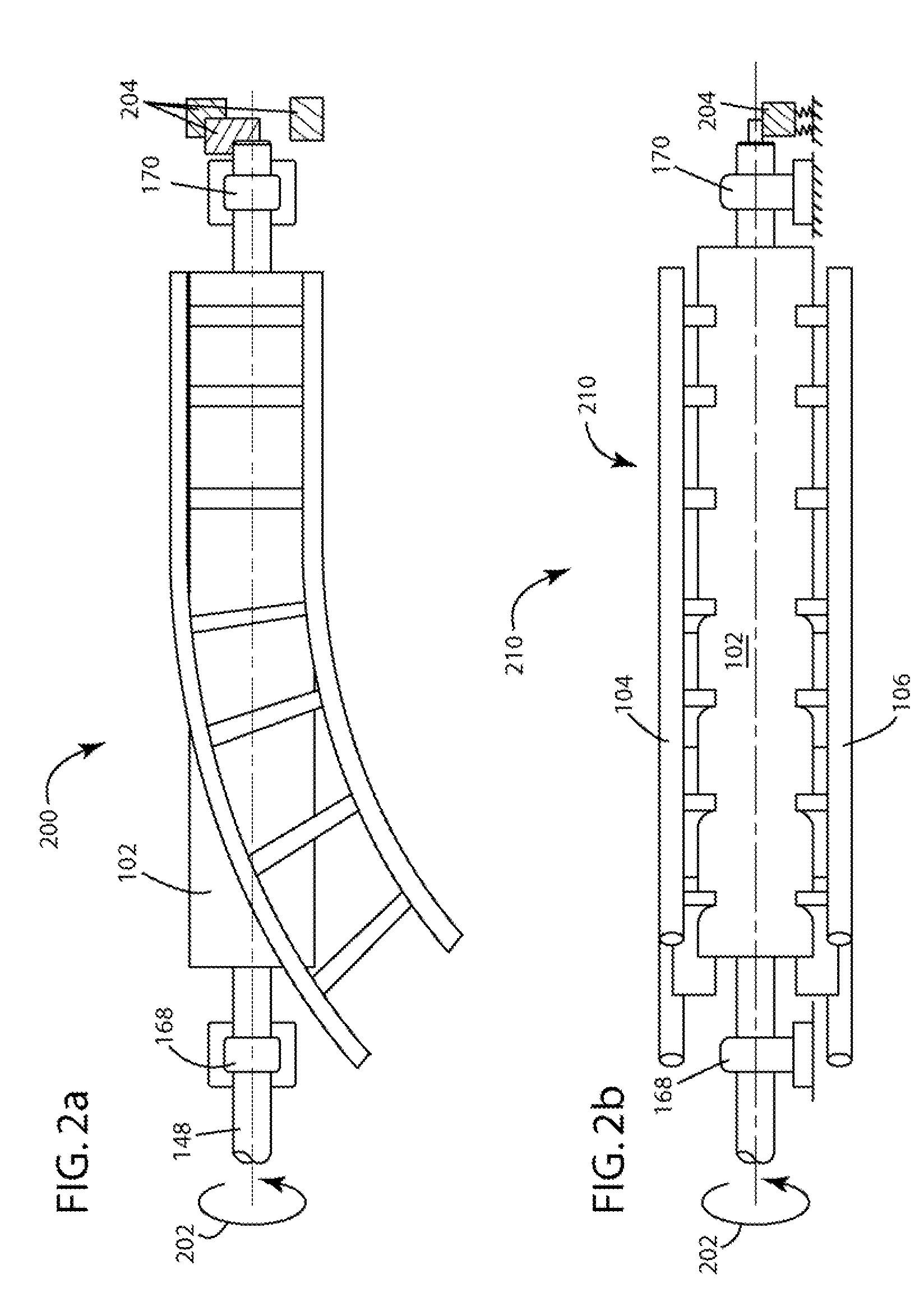
[0022]One embodiment of the present invention involves a track-switching device for switching a vehicle from a first track to a second track the track-switching device comprising a drive axle and a primary axel mechanically coupled by a looped belt. The drive axle comprises a barrel located at one end of the drive axle, the barrel having a plurality of switch tracks located thereon, and a braking assembly connected to the drive axle and spaced from the barrel. The primary axle is driven by a motor and comprises a flywheel and a clutch assembly, wherein the drive axle is driven by the primary axle via a looped belt, the drive axle being configured to rotate about an axis. One particular advantage afforded by this invention is the ability increase track-switching speed (i.e., less than 2 seconds) thereby increasing vehicle throughput.

[0023]Specific configurations and arrangements of the claimed invention discussed below with reference to the accompanying drawings are for illustrative ...


PUM


Abstract

The present disclosure provides an apparatus for switching a vehicle from a first track to a second track. The track-switching device may be rotated by a motor, and may have a drive axle and a primary axle. The drive axle may have a barrel located at one end of the drive axle, the barrel having a plurality of switch tracks located thereon and a braking assembly connected to the drive axle and spaced from the barrel. The primary axle may have a flywheel and a clutch assembly. The drive axle may then be driven by the primary axle upon engagement of the clutch assembly via the motor and the energy stored in the flywheel. A method for switching a vehicle from a first track to a second track is also provided.

Description

BACKGROUND[0001]The present invention relates to tracks for vehicles. More particularly, the present invention relates to a track-switching apparatus and a method for switching tracks.[0002]Since the early twentieth century, controlling the movement of vehicles that reside on tracks such as trains, intrafactory cargo vehicles, and amusement park rides has lead to important industrial growth and consumer satisfaction. In the case of amusement parks, as guests have demanded bigger, better, and more elaborate rides, they also require and expect a positive park experience, which entails progressively shorter and more rapidly moving lines to enter a ride.[0003]One technique to shorten wait times for lines involves increasing the throughput of vehicles on a track. The more vehicles that pass a given point on a track in a given time interval, the more guests are capable of being served. However, in rides that have multiple tracks and require vehicles to switch tracks, there exists a lag or...

Claims


Application Information

Patent Timeline
Patent Type & Authority Patents(United States)
IPC IPC(8): E01B25/00
CPCA63G7/00E01B7/08B61L5/065B61L5/02
Inventor BLUM, STEVEN C.
Owner UNIVERSAL CITY STUDIOS LLC
Why Eureka
Try Eureka