Screen assemblies utilizing screen elements retained in perforated supports

a technology of perforated supports and screen elements, applied in the direction of screening, solid separation, chemistry apparatus and processes, etc., can solve the problem of large screen surface area under-utilized, and achieve the effect of reducing any motion dampening effect, facilitating installation or change, and ensuring safety

Inactive Publication Date: 2011-09-20
HUKKI ARI M +1
View PDF10 Cites 14 Cited by
  • Summary
  • Abstract
  • Description
  • Claims
  • Application Information

AI Technical Summary

Benefits of technology

[0012]The present invention substantially increases the available area for screening compared to the available area of the prior art when a screen assembly creates a flat or crowned screening surface on a vibratory separator. Furthermore, the ease of replacing small, (typically three inches wide and 24 inches long) and lightweight (typically less than one pound) individual screen elements in the present invention saves time and material by eliminating the periodic replacement of large, heavy, and cumbersome screen assemblies in conventional vibratory separators. Typically these conventional screen assemblies weigh anywhere from 20 to 50 pounds and are approximately two to three feet long and up to four feet wide. In addition, when the present invention is used to replace hookstrip style screens with crowned screening surfaces, the effective screening area is increased by channeling the flow of unscreened material and preventing the pooling of liquid on either side of a crown deck. The crowned screen deck causes the processed material to flow away from the center of the screen (the crown) towards the sides, causing a large area of the screen surface to be under-utilized. In addition, the present invention facilitates storage and shipping of replacement screen elements because small, lightweight screen elements are stored and shipped rather than large, heavy screen assemblies. Furthermore, the present invention minimizes environmental impact by minimizing or eliminating the waste presently generated from disposal of screen assemblies. The screen elements of the present invention are easily recycled because the screen elements may have only stainless steel metallic components. The present invention improves the safety and speed with which screen elements can be replaced because small, lightweight screen elements are pressed into place as opposed to handling cumbersome and heavy screen frames. The present invention improves the economics of vibratory screening by allowing the replacement of individual screen elements rather than replacing the entire screen assembly in the event of a localized screen failure.
[0015]In contrast, the present invention describes a method of compressively holding the screen elements in the perforated screen supports and at the same time preventing any horizontal movement. The preferred screen element embodiment of the present invention includes a rigid frame formed to the inside diameter of the perforated screen support. The perforated screen support has an inwardly-extending flange on only one side. On the other side is a hold-down system that, when activated, pushes the screen element edge down and forces the screen element tightly against the inner surface of the perforated screen support. The inwardly-extending flange on the opposite side of the perforated screen support acts as a stop to prevent the screen element from climbing out of the perforated screen support. This greatly facilitates the removal and installation of the screen elements, and at the same time provides highly compressive hold down. This substantially eliminates potential process liquid bypass caused by loose fitting screen elements.
[0017]In a second aspect to the present invention, the perforation pattern of the perforated screen support is selected to maximize the non-blanked area (area available for screening) and optimize the strength and rigidity of the finished product.
[0020]In a fifth aspect of the present invention, a screen retention mechanism prevents the movement of screen element within the perforated screen support and minimizes any motion dampening effects from looseness of the screen element within the perforated screen support. In an alternate preferred embodiment, a pneumatic or hydraulic system, rather than a mechanical system may be used.
[0021]In a further separate aspect of the present invention, the screen supports will be attached to a structural frame constructed of stainless steel or another corrosion resistant material that can be installed in existing vibratory screeners for long periods of time or permanently.
[0022]Because the screen elements are smaller, lighter and easier to install or change than the screen elements used on prior art vibrating screeners, operators may handle these with greater safety from injury.

Problems solved by technology

The crowned screen deck causes the processed material to flow away from the center of the screen (the crown) towards the sides, causing a large area of the screen surface to be under-utilized.

Method used


Image

  • Screen assemblies utilizing screen elements retained in perforated supports
  • Screen assemblies utilizing screen elements retained in perforated supports
  • Screen assemblies utilizing screen elements retained in perforated supports

Examples


Embodiment Construction

[0044]Before the subject invention is further described, it is to be understood that the invention is not limited to the particular embodiments of the invention described below, as variations of the particular embodiments may be made and still fall within the scope of the appended claims. It is also to be understood that the terminology employed is for the purpose of describing particular embodiments, and is not intended to be limiting. Instead, the scope of the present invention will be established by the appended claims.

[0045]In this specification and the appended claims, the singular forms “a,”“an,” and “the” include plural reference unless the context clearly dictates otherwise. Unless defined otherwise, all technical and scientific terms used herein have the same meaning as commonly understood to one of ordinary skill in the art to which this invention belongs.

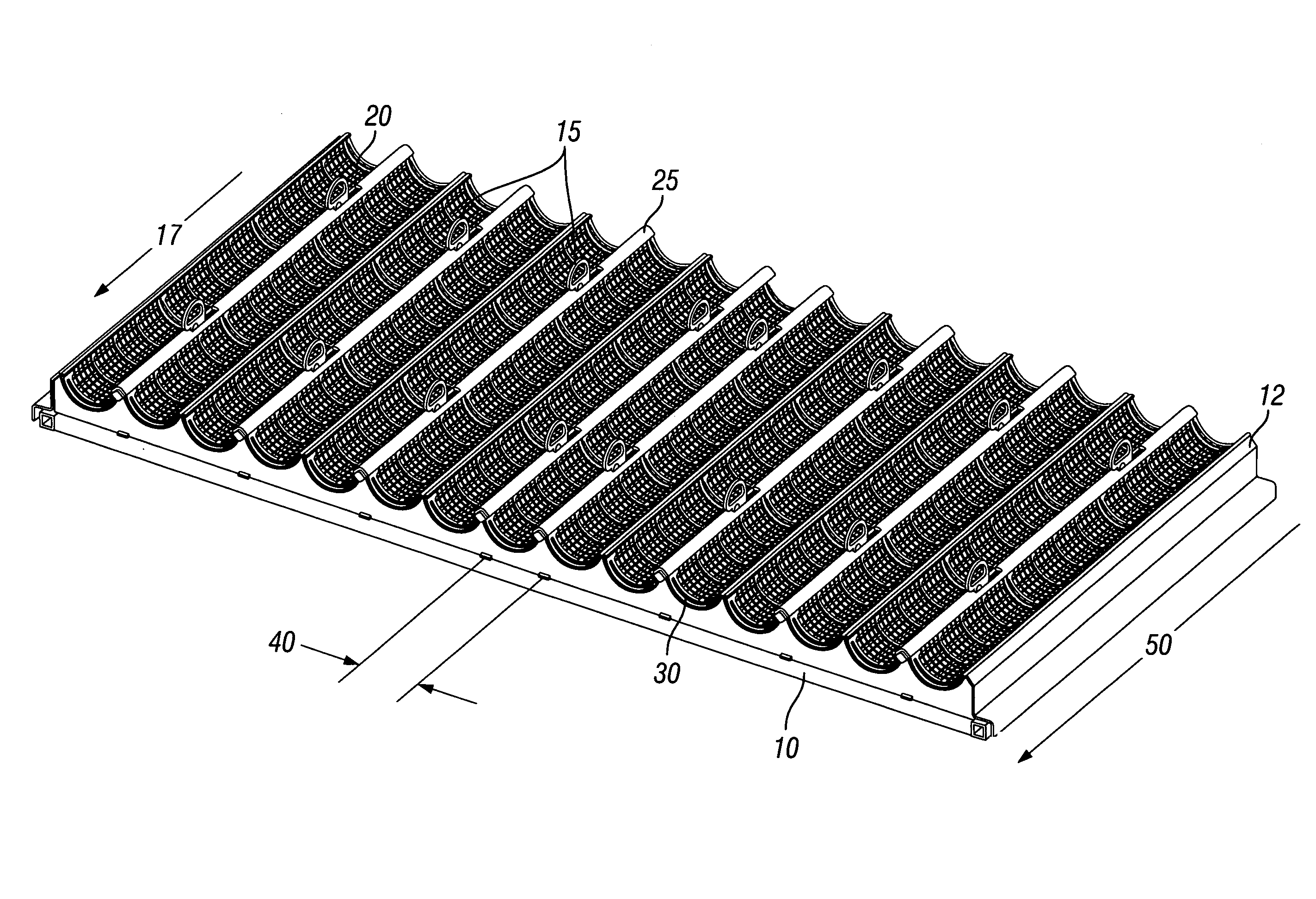
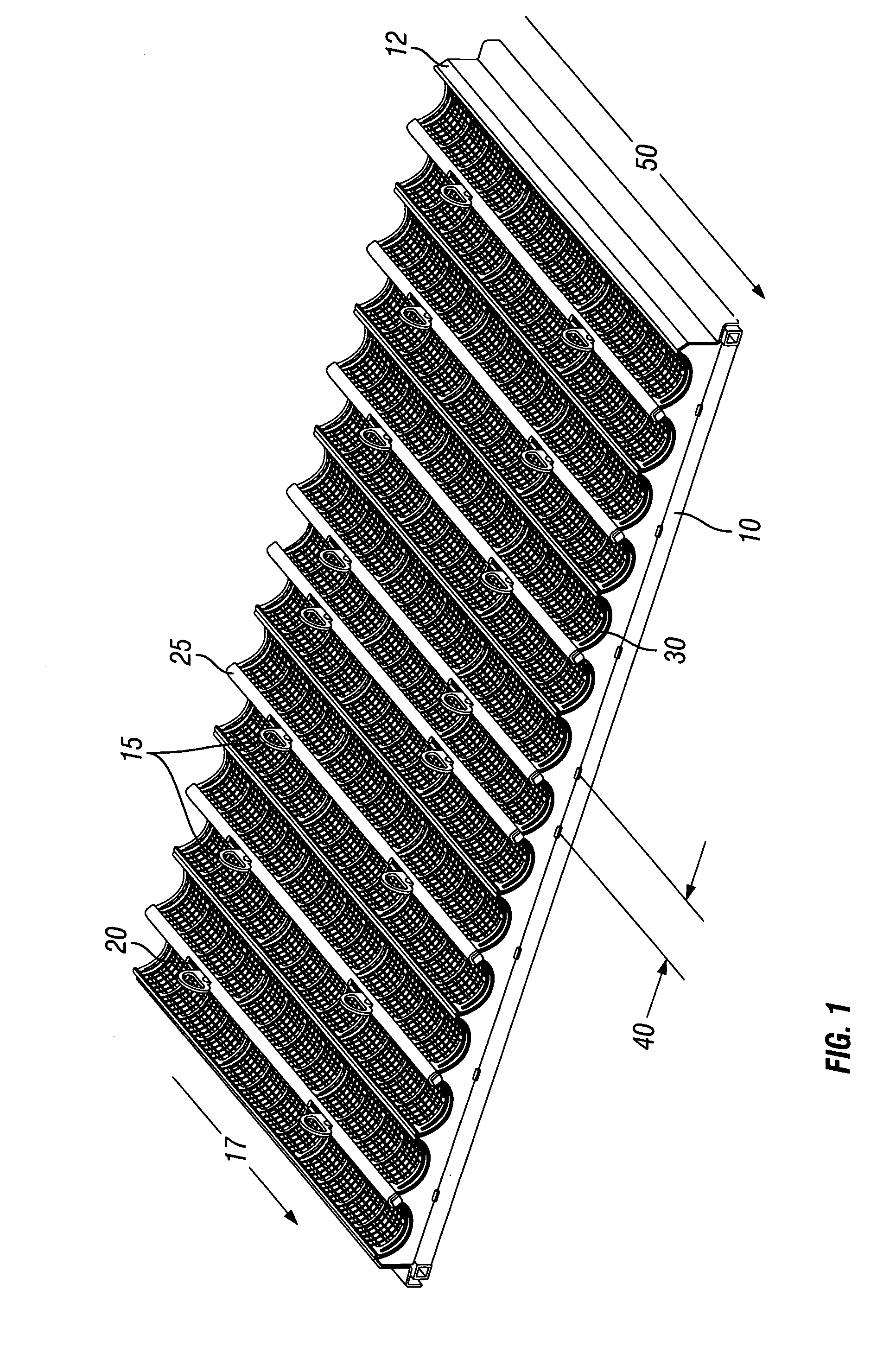
[0046]FIG. 1 illustrates a screen assembly (12) of a preferred embodiment of the present invention for use on vibratory...


PUM


Abstract

A screen retention mechanism for use with vibratory separators is disclosed. The screen retention mechanism includes a structural frame mounted to a vibratory separator into which a plurality of lightweight and flexible screen elements are inserted into multiple tows of perforated screen supports. The perforated screen supports are bonded to the structural frame and are aligned parallel to the direction in which solids are conveyed by a vibratory motion. The invention further features an improved retention mechanism whereby screen elements are conveniently and selectively restrained.

Description

CROSS-REFERENCE TO RELATED APPLICATIONS[0001]This Non-Provisional patent application, filed under 35 U.S.C. §111(a), claims the benefit under 35 U.S.C. §119(e)(1) of U.S. Provisional Patent Application No. 60 / 838,565, filed under 35 U.S.C. §111(b) on Aug. 18, 2006, and which is hereby incorporated by reference in its entirety. This Non-Provisional patent application is related to U.S. application Ser. No. 10 / 922,342, entitled “Screen assemblies utilizing screen elements retained in perforated troughs,” and filed on Aug. 20, 2004, and to U.S. Provisional Patent Application No. 60 / 839,141, entitled “Screen element,” and filed Aug. 16, 2006.STATEMENT REGARDING FEDERALLY SPONSORED RESEARCH OR DEVELOPMENT[0002]Not applicable.THE NAMES OF THE PARTIES TO A JOINT RESEARCH AGREEMENT[0003]Not applicable.INCORPORATION-BY-REFERENCE OF MATERIAL SUBMITTED ON COMPACT DISC[0004]Not applicable.BACKGROUND OF THE INVENTION[0005]1. Field of the Invention[0006]The present invention relates generally to ...

Claims


Application Information

Patent Timeline
Patent Type & Authority Patents(United States)
IPC IPC(8): B07B1/46
CPCB07B1/4654
Inventor HUKKI, ARI M.LILIE, GLENN T.
Owner HUKKI ARI M
Why Eureka
Try Eureka