Syringe spring retainer

a technology for syringes and retainers, which is applied in the field of syringe spring retainers, can solve the problems of high cost to society of supporting and providing medical attention, unclean needles and syringes, and unsanitary needles, and achieve the effect of improving the tactile properties of syringe users

Active Publication Date: 2011-09-20
UN HOLDINGS LLC
View PDF25 Cites 63 Cited by
  • Summary
  • Abstract
  • Description
  • Claims
  • Application Information

AI Technical Summary

Benefits of technology

[0007]Therefore, in a broad form the present invention provides a spring retainer for a syringe that provides efficient retraction of a spent needle into the barrel of a retractable syringe while also having improved tactile properties to a syringe user.
[0013]According to this embodiment, disengagement of said first body member and second body member allows or facilitates decompression of said spring.
[0017]Preferably, disengagement of said first body member and second body member is accompanied by rotation of said second body member relative to said first body member, which in turn assists rotation of said plunger, when said retractable needle is coupled therewith, into a final, inoperable position.

Problems solved by technology

The problems of shared syringes are notorious.
The practice of sharing syringes without adequate sterilisation between successive users is a major contributor to the transfer of Human Immunodeficiency Virus and Hepatitis with subsequent severe repercussions for the sufferer of such diseases and at a high cost to society of supporting and providing medical attention to those sufferers.
A lesser but still significant risk associated with unclean needles and syringes arises from the possibility of inadvertent needle-stick injuries.
This is particularly a problem for law enforcement officers and paramedics who often encounter users of illegal drugs in their professional activities.
Additionally, the habits of illegal drug users are such that dangerous by-products of their activities, such as discarded syringes, are often left in places of public access presenting a risk to the users of areas such as public parks and school grounds.
However, resistance by the spring during plunger depression provides an undesirable “feel” to some syringe users, such as intravenous drug users.

Method used


Image

  • Syringe spring retainer
  • Syringe spring retainer
  • Syringe spring retainer

Examples


Embodiment Construction

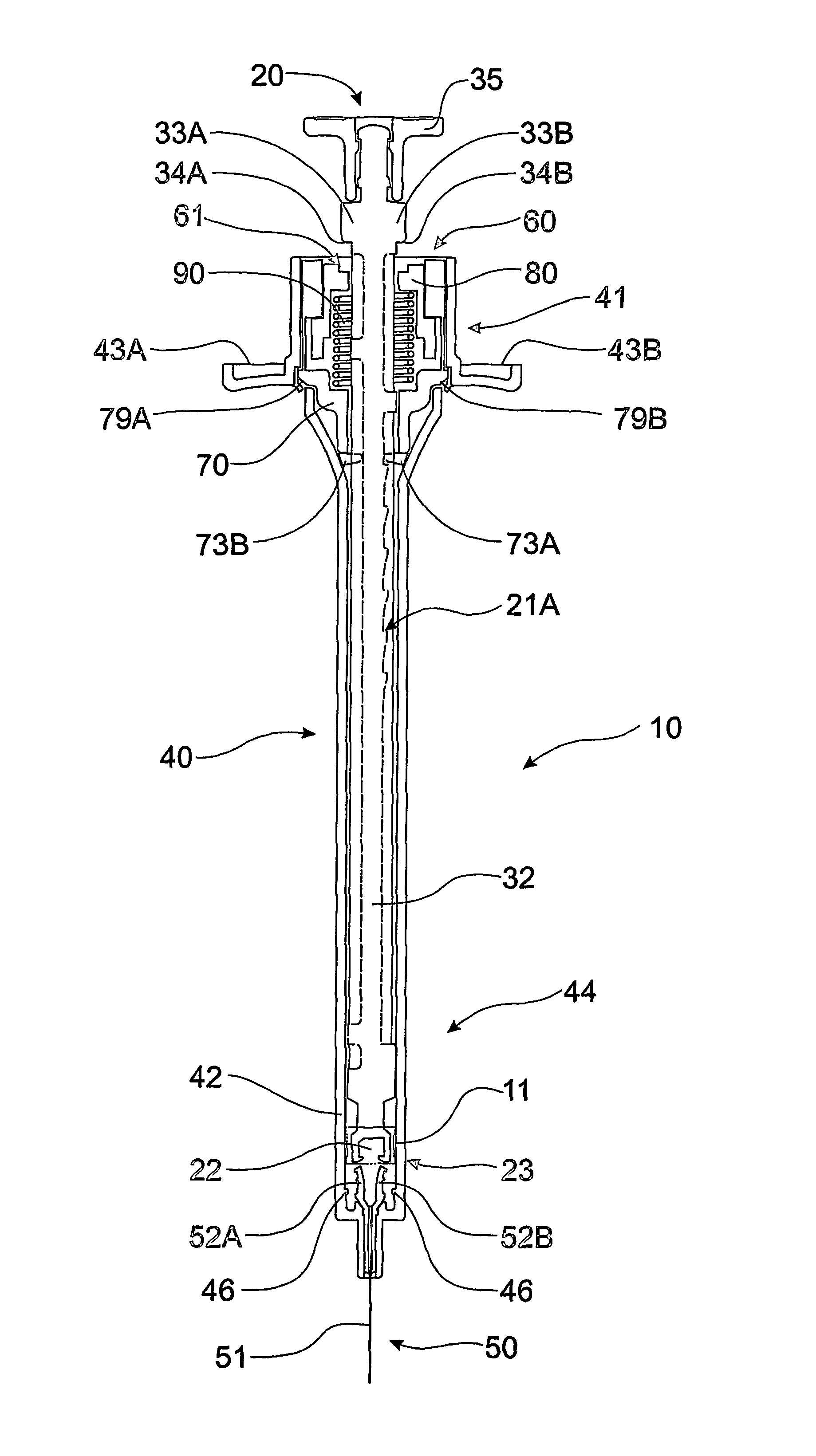
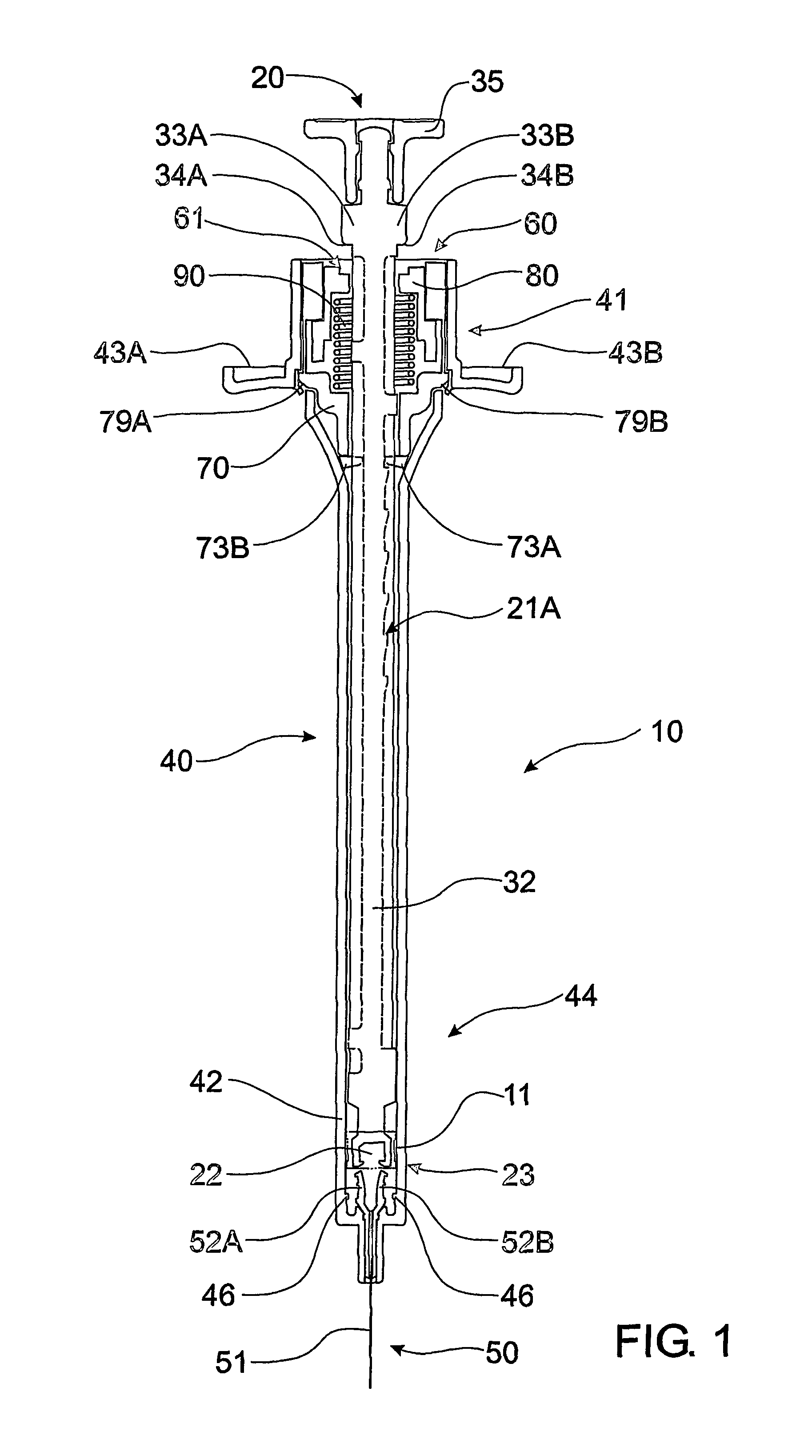
[0027]It will be appreciated that herein is described an embodiment of a single use retractable syringe 10 comprising in part, components based on those originally described in International Publication WO 01 / 80930, Australian Patent 731159 and U.S. Pat. No. 6,083,199, each of which is incorporated herein by reference.

[0028]Referring to FIG. 1 and FIG. 2, syringe 10 has plunger 20, barrel 40, retractable needle 50 and spring retainer 60. Spring retainer 60 is located in flared end 41 of barrel 40, and comprises first body member 70 and second body member 80 that co-operate to house and maintain spring 90 in the initial compressed state shown in FIG. 1. Syringe 10 also comprises seal 11 located on plunger 20, which prevents leakage fluid between plunger 20 and internal wall 42 of barrel 40.

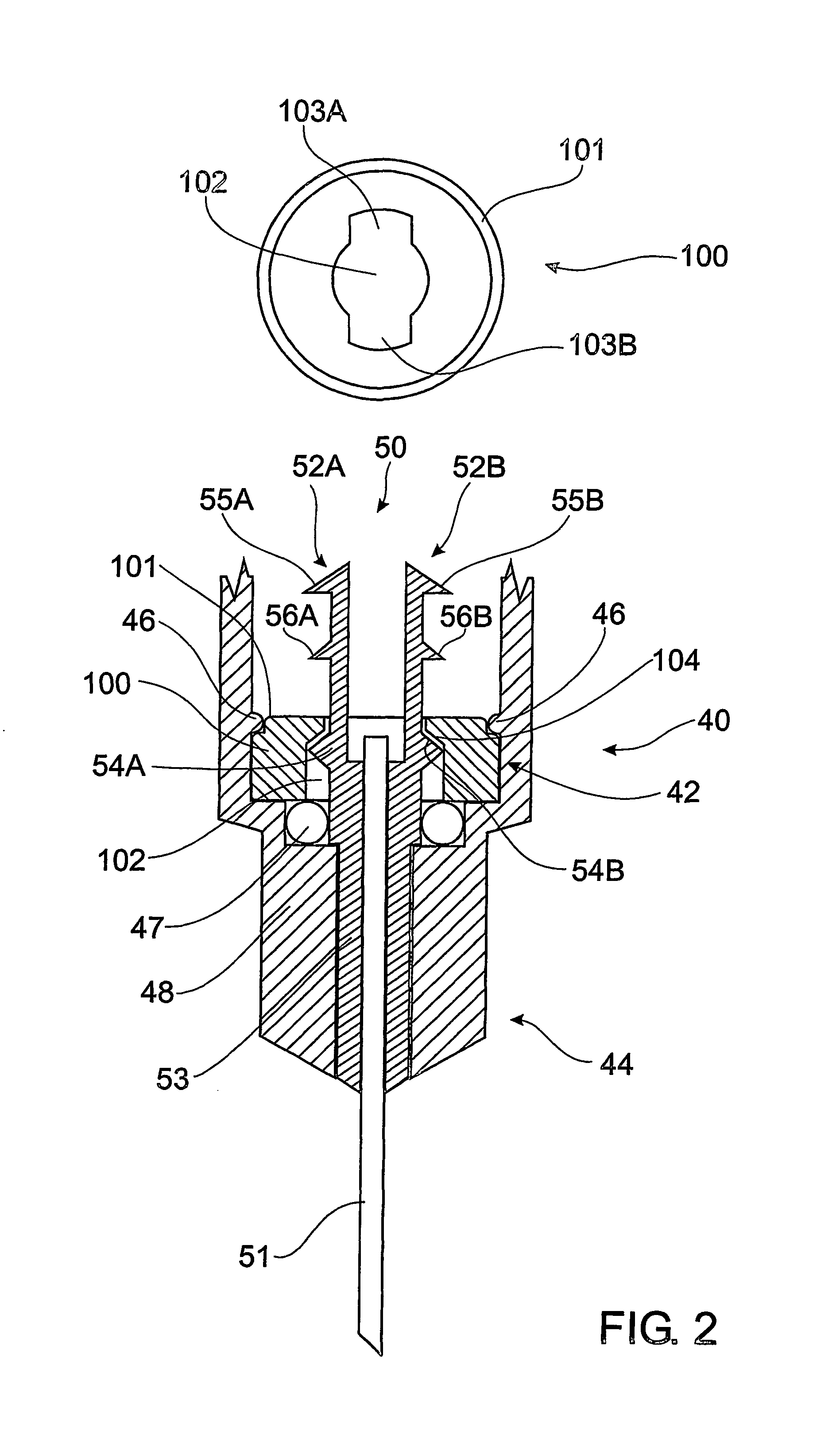
[0029]Retractable needle 50 is mounted at needle end 44 of barrel 40 and comprises cannula 51 and barbed arms 52A, 52B mounted to body 53 that are engageable by respective barb-engaging apertures 2...


PUM


Abstract

A spring retainer (60) for a syringe (10) that has a barrel (40), a plunger (20), a spring (90) and a retractable needle (50) that can couple with the plunger for spring-driven retraction of the coupled needle and plunger. The spring retainer has first (70) and second (80) body members that cooperate to releasably maintain the spring in a compressed state until the plunger is coupled to the retractable needle after depression of the plunger to deliver the fluid contents of the syringe. Depression of the plunger triggers rotational disengagement of the first and second body members to allow decompression of the spring which forces retraction of the needle into the barrel. Rotational disengagement of the first and second body members also assists rotation of the plunger into a final, inoperable position.

Description

[0001]This application is a national stage application under 35 U.S.C. §371 from PCT Application No. PCT / AU2004 / 000354, filed Mar. 19, 2004, which claims the priority benefit of Australian Application Nos. 2003901301, filed Mar. 20, 2003 and 2003905080, filed Sep. 18, 2003.FIELD OF THE INVENTION[0002]THIS INVENTION relates to a spring retainer for a syringe. More particularly, this invention relates to a spring retainer for a single-use, retractable syringe that facilitates prevention of syringe and / or needle re-useBACKGROUND OF THE INVENTION[0003]The problems of shared syringes are notorious. The practice of sharing syringes without adequate sterilisation between successive users is a major contributor to the transfer of Human Immunodeficiency Virus and Hepatitis with subsequent severe repercussions for the sufferer of such diseases and at a high cost to society of supporting and providing medical attention to those sufferers.[0004]A lesser but still significant risk associated wit...

Claims


Application Information

Patent Timeline
Patent Type & Authority Patents(United States)
IPC IPC(8): A61M5/00A61M5/315A61M5/32
CPCA61M5/3234A61M2005/3231
Inventor KAAL, JOSEPH HERMESTHORLEY, CRAIG STEPHEN
Owner UN HOLDINGS LLC
Why Eureka
Try Eureka