
Intelligent wireless power charging system

a wireless power charging and intelligent technology, applied in electromagnetic wave systems, transmission, substation equipment, etc., can solve the problems of insufficient capacity, inability to power existing wireless devices such as cell phones, portable computers, and inability to solve wire congestion problems,

Active Publication Date: 2011-09-20
INT BUSINESS MASCH CORP
View PDF33 Cites 38 Cited by
  • Summary
  • Abstract
  • Description
  • Claims
  • Application Information

AI Technical Summary

Benefits of technology

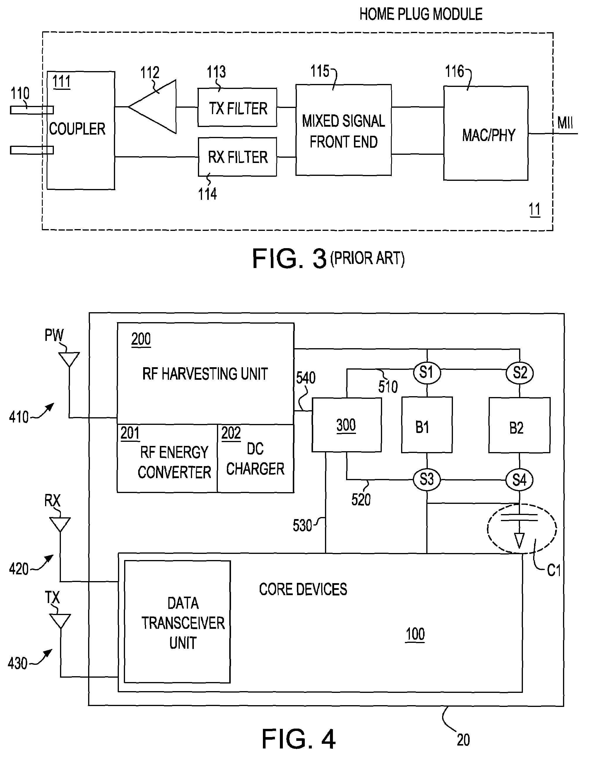
[0051]Thus, in the third embodiment, two chargeable energy storage devices (batteries) is provided in the wireless device—one battery being adapted as a backup. Therefore, in this embodiment, data transmission and receiving will not be interrupted by the power charging operations. In other words, batteries can be dynamically swapped, and with the aid of a capacitor device, to hold the charge during swapping. Thus, the wireless device will be maintained fully powered.

Problems solved by technology

However, wireless devices need power supply to keep them operational.
The passive power such as generated by an RFID transmit device however, can not be used to power existing wireless devices such as cell phone, portable computer, etc.
This method is now implemented to charge battery of electric tooth brushes, however, it does not solve the wire congestion problem, since wire is still needed for the reception system.
However, due to the lack of intelligent power charging system, a battery could be over charged or do not have enough capacity when the device is in usage.
Additional issues are that no warning system is provided when device is placed out of charging range and there is no mechanism to guarantee a reliable and continuous operation, since battery charging will interrupt data communication operation.
It may be used in a green house, but the battery will be depleted at night or during cloudy day.
It is not a reliable means to maintain power for devices such as cell phone or portable computers.

Method used


Image

  • Intelligent wireless power charging system
  • Intelligent wireless power charging system
  • Intelligent wireless power charging system

Examples


second embodiment

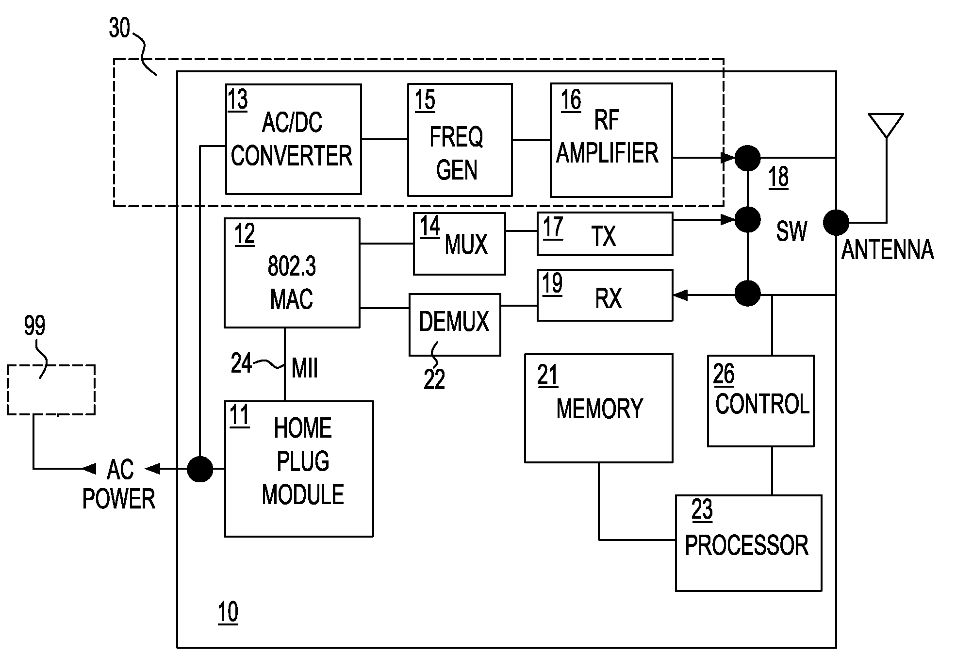
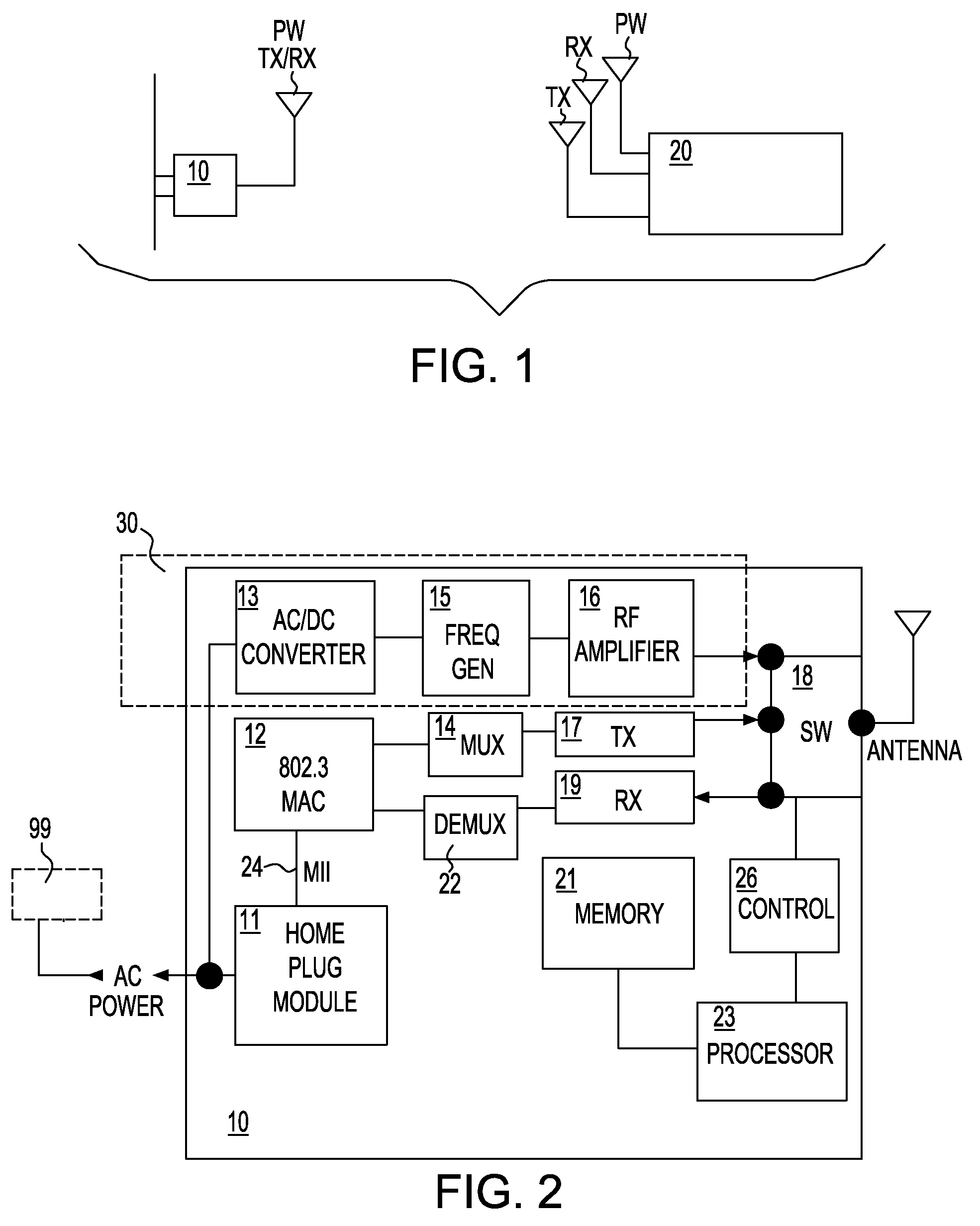
[0078]In a second embodiment, the invention is designed for use with wireless devices which are demanded for semi-active data communication. In this example, two HomePlug® adaptors 10A and 10B are implemented as shown in FIG. 6. A first HomePlug® is served as the master adaptor 10A used mainly for data communication. The second adaptor 10B is called the slave adaptor is mainly used for power transmission. Therefore the wireless device 20 should be located within a certain range of two adaptors such that it can receive simultaneous transmissions. This “dual plug” (master and slave plug) system provides low-noise to the wireless device, as the power charging signals and data signals are from different adaptors.

[0079]FIGS. 7A and 7B depict two flow chart diagrams implementing respective state-machine control of two home adaptors operating according to a second embodiment of the invention. To keep power charging more effectively, the wireless device must first be placed within a certain...

third embodiment

[0082]the invention is depicted in FIG. 8 wherein two adaptors are employed and two batteries are installed in the wireless device 20. This configuration may be advantageously employed for highly active wireless devices. The data traffic is very busy and there is almost no standby mode for battery charging. The algorithm starts out by checking the effective power charge range. The wireless device sends a signal to the home adaptor plug and waits for a response 801. If the received signal is poor or not acceptable, 802 a visual or audible warning signal will be triggered 803 to warn the users. If the signal strength is acceptable the intelligent will start checking the primary battery level and determine whether it is higher than the lower level of an acceptable charge range. If the charge level is higher than a set lower level, then battery swapping is taking place 805, and immediately the primary battery is subjected to a charging operation 806. It will continue to charge the prima...


PUM


Abstract

A system and methodology for intelligent power management of wirelessly networked devices. The system provides for reliable wireless communication via a wireless power charging method and, a method to maintain power capacity of batteries in a wireless device. The batteries are charged via an RF harvesting unit embedded inside the wireless device. An intelligent wireless power charging system further comprises at least two batteries and at least two RF adaptor devices coupled to an AC power line. The first adaptor is set for data communication while the second adaptor is used to transmit the power. In addition, when a first battery is in use during active mode, the second battery is subjected to wireless charging.

Description

FIELD OF THE INVENTION[0001]The present invention generally relates to a wireless power charging system and, more particularly, to system and method for providing wireless intelligent charging for wireless networked devices.BACKGROUND OF THE INVENTION[0002]Networking of small offices and homes are increasing in popularity. For example, in a home office, it is strongly desired to have the ability to inexpensively and reliably interconnect multiple network devices without having to install Ethernet or twisted pair backbone wiring. These network devices, for example, include personal computer, lap-top computers, printer, digital TV, set-top box, home appliances, etc. To achieve this, both wireless solutions and Internet on-power line solutions (e.g., according to the HomePlug® industry solution) have been considered as the physical layer backbone for such networking.[0003]As known, the HomePlug® makes use of the existing in-home AC power wires for transmitting signal data at high speed...

Claims


Application Information

Patent Timeline
Patent Type & Authority Patents(United States)
IPC IPC(8): H04B1/38H04B1/16
CPCH02J17/00H02J50/20H02J50/80H02J50/001H02J50/005H02J50/40H02J7/0049H02J7/0044H02J2310/22
Inventor CLEVENGER, LAWRENCEDALTON, TIMOTHYHSU, LOUISRADENS, CARL
Owner INT BUSINESS MASCH CORP
Learn More