
Detritus flow management features for drag bit cutters and bits so equipped

a technology of detritus flow and drag bit cutter, which is applied in the field of drill bits, can solve the problems of affecting cutting performance, affecting the cutting performance, and adding to the fabrication cost of cutting elements, so as to inhibit the flow and buildup of detritus, increase the permeability, and improve the effect of permeability

Active Publication Date: 2011-09-27
BAKER HUGHES INC
View PDF20 Cites 0 Cited by
  • Summary
  • Abstract
  • Description
  • Claims
  • Application Information

AI Technical Summary

Benefits of technology

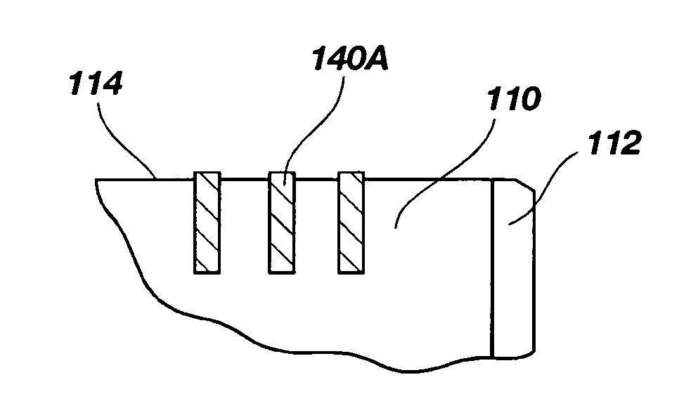
The invention provides modifications to the structure of PDC cutting elements to prevent the buildup of detritus (debris) on the side surface of the cutter barrel. These modifications include texturing or roughening the side surface, adding structures to the side surface, or increasing the permeability of the side surface. These modifications allow hydrostatic pressure to invade between the side surface and the detritus, preventing it from adhering to the cutter barrel. This results in improved performance of the cutting element by reducing the flow and buildup of detritus.

Problems solved by technology

In some instances, such as when a portion of the PDC table adjacent the cutting face has been leached of the metal catalyst used to stimulate diamond-to-diamond bonding during formation of the PDC table, a lip may form during drilling due to more rapid wear of the unleached portion of the PDC table to the rear of the leached portion.
Researchers in the industry have recognized that controlling buildup of recompacted rock cuttings, or detritus, on the cutting face of a PDC cutter is a significant factor affecting cutting performance.
Moreover, configuring a PDC cutting element with, or to form, a protruding lip adds cost to cutting element fabrication and the increased cost of such cutting elements may not be perceived to be commensurate with the benefits obtained for many applications.

Method used


Image

  • Detritus flow management features for drag bit cutters and bits so equipped
  • Detritus flow management features for drag bit cutters and bits so equipped
  • Detritus flow management features for drag bit cutters and bits so equipped

Examples


Embodiment Construction

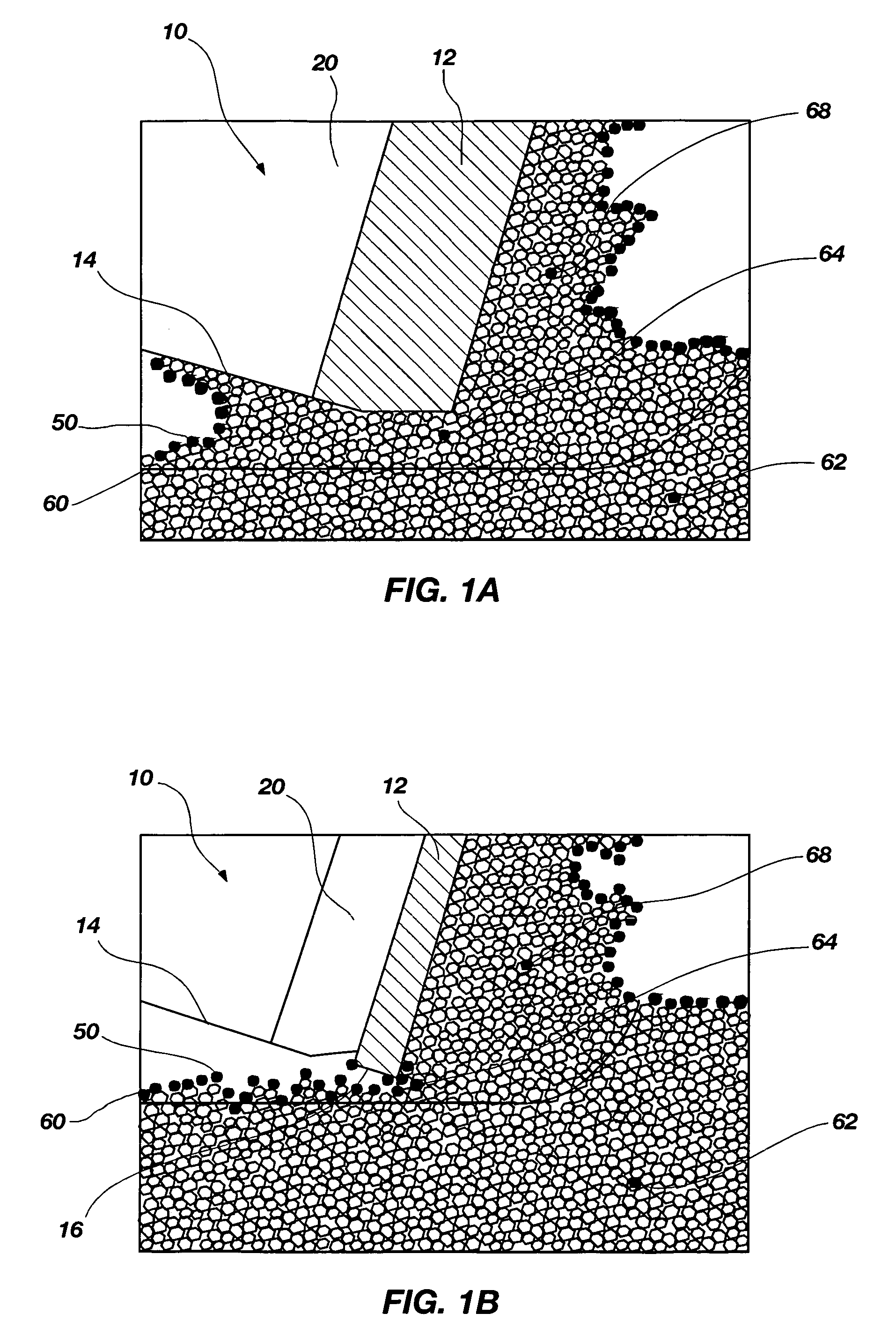
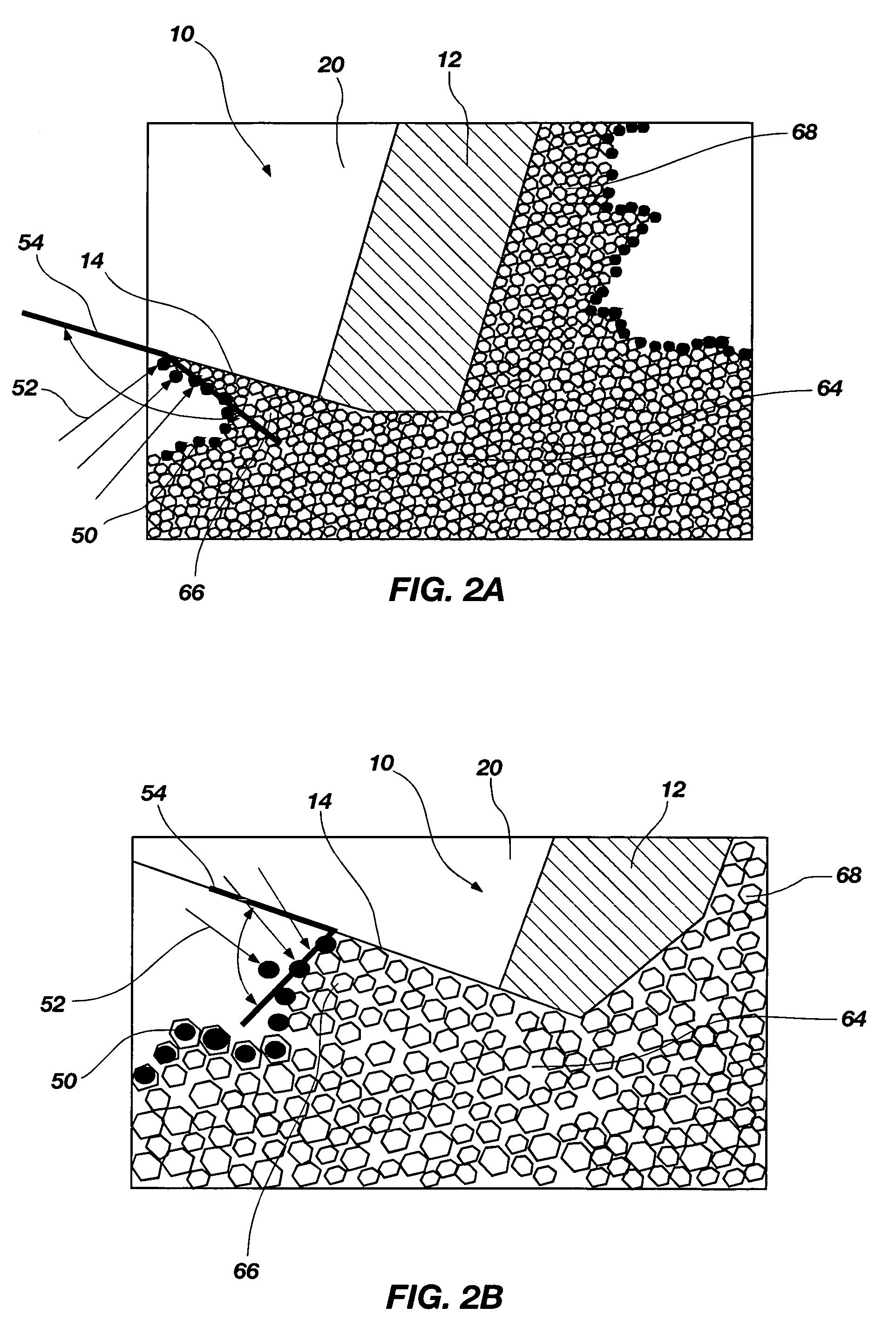
[0029]It has been found that the recompacted rock detritus can have a confined strength on the same order of magnitude as virgin rock, and Particle Flow Code (PFC) models used in Discrete Element Modeling (DEM) of rock formations show that most of the energy in rock cutting using a fixed cutter is expended while extruding the recompacted detritus. Particle Flow Code is produced by Itasca Consulting Group, Inc., of Minneapolis, Minn.

[0030]Additionally, PFC models show that the flow of detritus under the cutter (between the cutter and the formation being cut) is equally as important as the flow of detritus on the cutter face. This role of detritus flow affecting the cutting mechanism, and the consequent potential for differential sticking to the cutter barrel, which impairs cutter access to the formation being drilled and significantly reduces cutting efficiency, has previously gone unrecognized in the art. Innovations that affect the flow of detritus under the cutter offer opportunit...


PUM


Abstract

Rock detritus created by a drag bit cutter shearing subterranean formation material may flow under a cutter and attach itself to a side surface of a cutter barrel by differential pressure-induced sticking, and dilate. This attached material, confined by hydrostatic pressure, can create and strengthen a barrier between the cutter and virgin rock being cut. The detritus barrier absorbs bit weight and reduces cutter efficiency by impairing contact of the cutter with the virgin rock formation. Increasing friction between the rock detritus and the side surface of the cutter barrel inhibits detritus flow, reduces build up, and allows hydrostatic pressure to contribute to, rather than inhibit, the cutting process. Similar beneficial results may be obtained when hydrostatic pressure drilling fluid is permitted to communicate through holes in the side surface of the cutter, or through an otherwise permeable side surface alleviating detritus sticking due to differential pressure effects.

Description

FIELD OF THE INVENTION[0001]This invention relates generally to drill bits for drilling subterranean formations and, more specifically, to cutters for drilling such formations and drill bits so equipped.BACKGROUND OF THE INVENTION[0002]Rotary drag bits have been used for subterranean drilling for many decades, and various sizes, shapes, and patterns of natural and synthetic diamonds have been used on drag bit crowns as cutting elements, or cutters. When drilling certain subterranean formations, a properly designed drag bit can provide an improved rate-of-penetration (ROP) over a tri-cone bit.[0003]Rotary drag bit performance has been improved significantly with the introduction of polycrystalline diamond compact (PDC) cutting elements, usually configured with a substantially planar PDC table formed onto a cemented tungsten carbide substrate under high-temperature and high-pressure conditions. PDC tables are formed into various shapes, including circular, semicircular, and tombstone,...

Claims


Application Information

Patent Timeline
Patent Type & Authority Patents(United States)
IPC IPC(8): E21B10/46
CPCE21B10/573E21B10/54
Inventor LEDGERWOOD, III, LEROY W.
Owner BAKER HUGHES INC
Learn More