

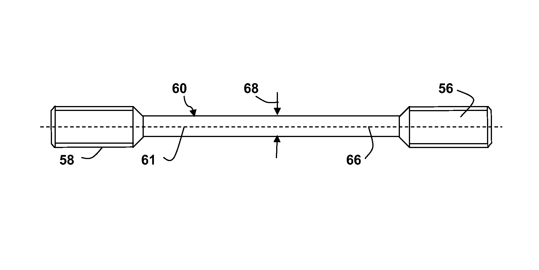
Wind turbine blade attachment configuration with flattened bolts
a technology of flattened bolts and wind turbine blades, which is applied in the direction of threaded fasteners, screwdrivers, liquid fuel engines, etc., can solve the problems of considerable bending of blades, extreme loads and fatigue stresses placed on the rotor blades of these turbines, and contribute to the total stress placed on the blades. , to achieve the effect of reducing extreme load strength, and maximizing extreme load strength
- Summary
- Abstract
- Description
- Claims
- Application Information
AI Technical Summary
Benefits of technology
Problems solved by technology
Method used
Image

Examples
Embodiment Construction
[0023]Reference now will be made in detail to embodiments of the invention, one or more examples of which are illustrated in the drawings. Each example is provided by way of explanation of the invention, not limitation of the invention. In fact, it will be apparent to those skilled in the art that various modifications and variations can be made in the present invention without departing from the scope or spirit of the invention. For instance, features illustrated or described as part of one embodiment can be used with another embodiment to yield a still further embodiment. Thus, it is intended that the present invention include such modifications and variations as come within the scope of the appended claims and their equivalents.
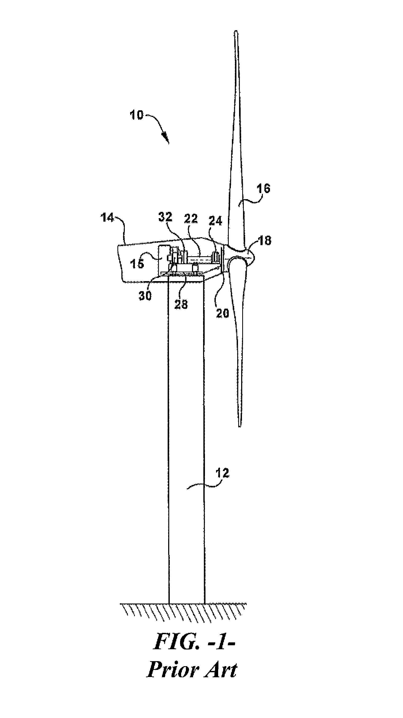
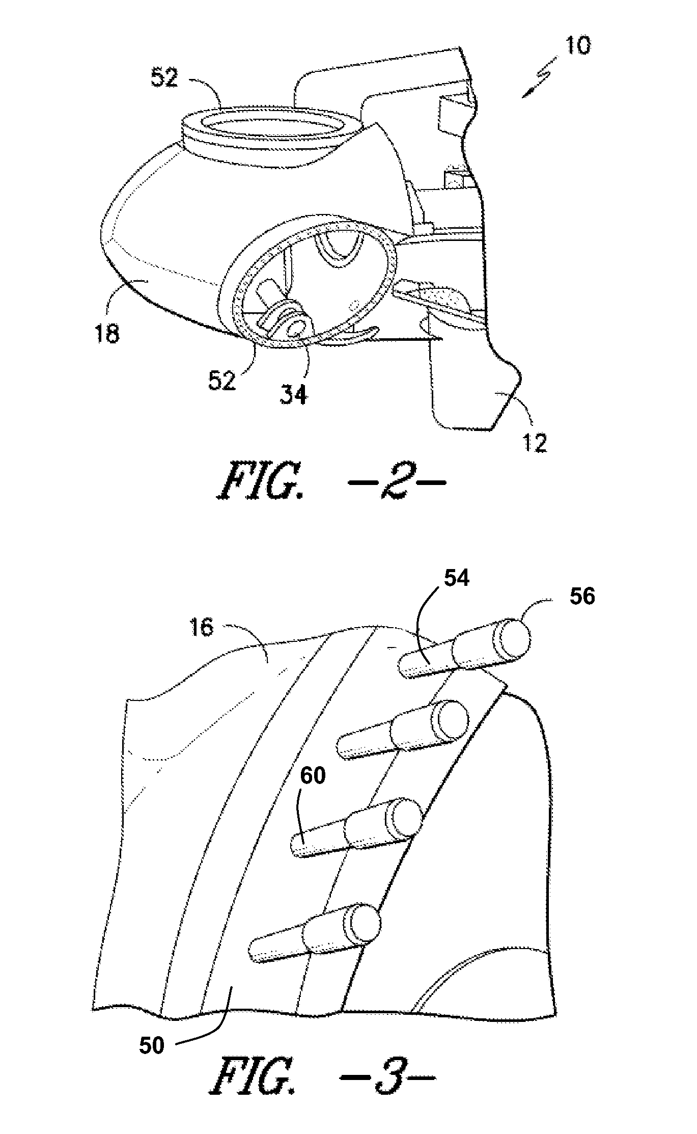
[0024]FIG. 1 illustrates a wind turbine 10 of conventional construction. The wind turbine 10 includes a tower 12 with a nacelle 14 mounted thereon. A plurality of turbine blades 16 are mounted to a rotor hub 18, which is in turn connected to a main flange ...
PUM
 Abstract
Description
Claims
Application Information